
1Safety
1.1Safety Icons
Pay attention to the following icons and their meanings. Failure to follow these guidelines can result in equipment damage or personal injury.
| WARNING | Not following these instructions may lead to minor injuries. |
| CAUTION | Not following these instructions may lead to major injuries. |
| DANGER | Not following these instructions may lead to serious injuries or death. |
1.2Safety Guide
Prohibited:
- Do not fly at night or in bad weather like rain or thunderstorm. It can cause erratic operation or loss of control.
- Do not use the product when the visibility is limited.
- Do not use the product on rainy or snowy days. Should any type of moisture (water or snow) enter any component of the system, erratic operation and loss of control may occur.
- Interference could cause loss of control. To ensure the safety of you and others, do not operate in the following places: near any site where other radio control activity may occur; near high voltage power lines or communication broadcasting antennas; near water with passenger boats nearby; near high voltage wires or communication/broadcast antennas.
- Do not use this product if you are tired, uncomfortable or when using substances that may impair your ability to use the product safely.
- The 2.4GHz frequency band requires line of sight from the transmitter to receiver at all times. Avoid large obstacles that could block or interfere with the signal.
- In order to ensure good signal quality, do not hold the transmitter's antenna during use.
- Parts of the model, such as motors or ESCs, may remain hot for a period of time after use and can cause severe burns.
Mandatory:
- Improper use of this product may lead to serious injury or death to the user and others. To ensure the safety of yourself and others read and follow the instructions set out in the user manual.
- To avoid damage to the model, make sure that the product and model are installed correctly before use.
- Always power off the receiver before the transmitter. Powering off the receiver before the transmitter could lead to loss of control.
- Before use make sure that all the servos and motors are moving in the correct direction.
- Make sure to remain within range to prevent loss of control.
2Battery Safety Instructions
Danger:
- This product's battery is rechargeable and non-removable. Do not remove the battery from the product.
- Do not charge batteries that show any evidence of damage, aging, leakage or exposure to liquids.
- Do not expose the battery to liquids. Do not use a damp battery. Keep your hands dry during use and do not leave batteries in areas with lots of moisture.
- Do not tap the positive and negative terminals of the battery together.
- Do not solder, repair, modify or disassemble the battery.
- Do not throw the battery into a fire.
- Do not charge the battery in direct sunlight, in a hot car or near anything hot such as cookers etc.
- Do not charge without ventilation.
- Do not use near flammable liquids or gasses.
- Charge the transmitter battery before use. If there is not enough quantity of electricity during the flight, it will lead to an airplane crash.
Warning:
- Do not tap the charger or battery during charging. May cause burns.
- Do not throw or impact the battery. May cause fire or an explosion.
- Keep the battery away from any heat source if it is leaking or causing strange smells. May catch fire or explode.
- Put some tape on the battery's terminals before recycling. If the short circuit causes fire, heat, rupture, etc.
- Do not store the battery in dusty or humid environments. Remove dust from the power connector before plugging in.
- Do not charge the battery when exposed to extreme heat or cold. May lead to a drop in battery performance. To ensure maximum performance always charge the battery within the temperature range of 10 ℃ ~ 30 ℃.
3Product Description
The PL18 Ultra transmitter is a comfortable and ergonomic air transmitter. It features the 2.4GHz AFHDS 3 (third-generation Automatic Frequency Hopping Digital System) protocol, offering 18-channel communication. This transmitter is compatible with the RM303 RF module to support various communication protocols and can store up to 50 model setups. It includes a variety of built-in model type setting menus, enabling flexible adaptation to different RC models such as airplanes, gliders, helicopters, multicopters, cars, boats, and robots.
3.1System Features
AFHDS 3 (third-generation automatic frequency hopping digital system) is a newly developed digital wireless system with independent intellectual property rights by FLYSKY. It is compatible with one-way and two-way real-time data packet transmission and transparent data stream transmission. In other words, this system has advantages of both AFHDS 2A and WS2A wireless system. It equips with a brand-new 2.4G chip, stable and reliable connection, good real-time performance, and supports various configurations. Bring you the optimal configuration for multi-scenario application performance.
| Compatible with Unidirectional/Bidirectional Real-time Data Transmission | The system supports one-way and two-way connections. When the transmitter is working in one-way transmission way, the receiver can receive data from the transmitter. When the transmitter is working in two-way transmission way, the receiver can receive data from the transmitter and the transmitter can also receive data from the receiver, as well as the information cross from the temperature and speed sensor modules. |
| Data Transparent Transmission | The independent data transparent transmission module is built into RF system, which can realize data transmission via transmitter and transparent transmission. It can be used for data transmission of flight control. |
| Intelligent RF configuration | To set the parameters which affect RF transmission distance, speed and anti-interference, such as numbers of channels, resolution, bandwidth and receiver sensitivity. The system can be set according to different application requirements to obtain the most suitable performance. |
| Multi-channel Frequency Hopping | This system's bandwidth ranges from 2.402GHz to 2.480GHz. Set intelligent RF configurations according to your requirements, it can avoid or reduce the interference from other transmitters with the same frequency via different configurations, different time of powering on the transmitter, various patterns to the hopping frequency and various using frequency spots. |
| Unique ID Recognition System | Each transmitter and receiver has its own unique ID. Once the transmitter and receiver have been bound, they will save each other's ID and only connect with each other. When the system is working, if the IDs are matched with each other, then the connection will be connected, otherwise, there is no connection between transmitter and receiver. This unique ID recognition system resists the interference so as to make the system stabler and more reliable. |
| Low Power Consumption | It is built using highly sensitive, low power consumption components. And it works in the way of interval data transmission to improve transmitting efficiency effectively and extend the working time of the battery distinctly, while it consumes as little as one tenth the power of a standard FM system. |
3.2Transmitter Overview
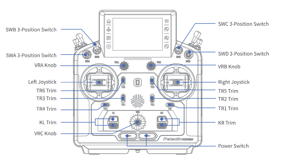
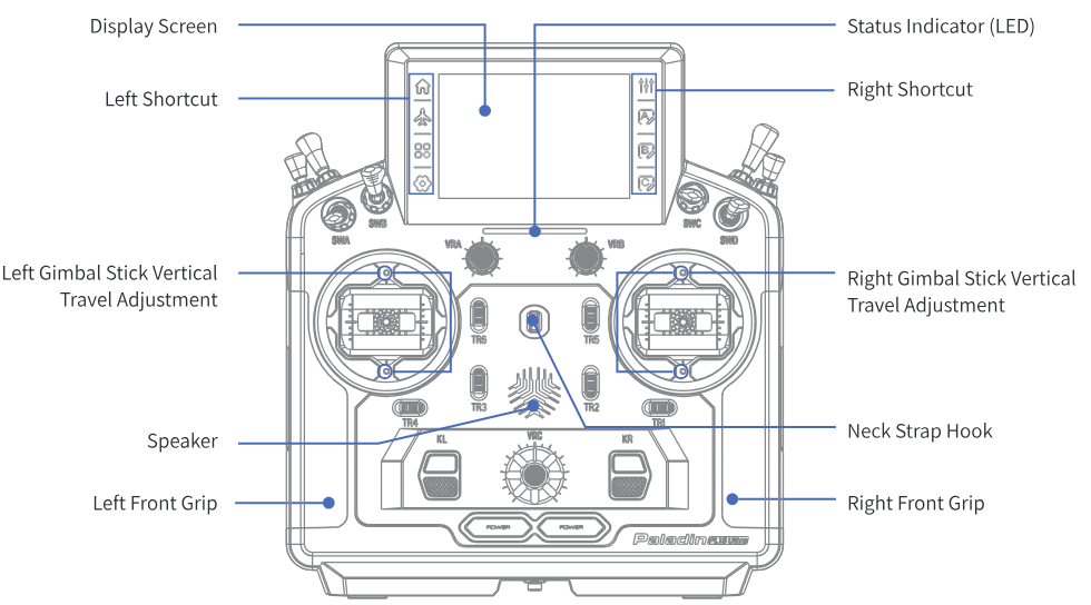
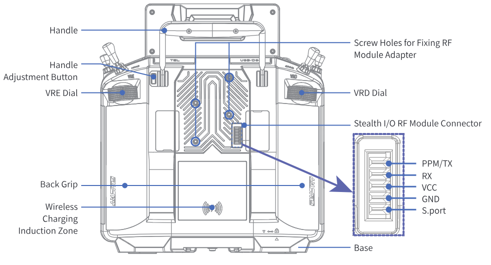
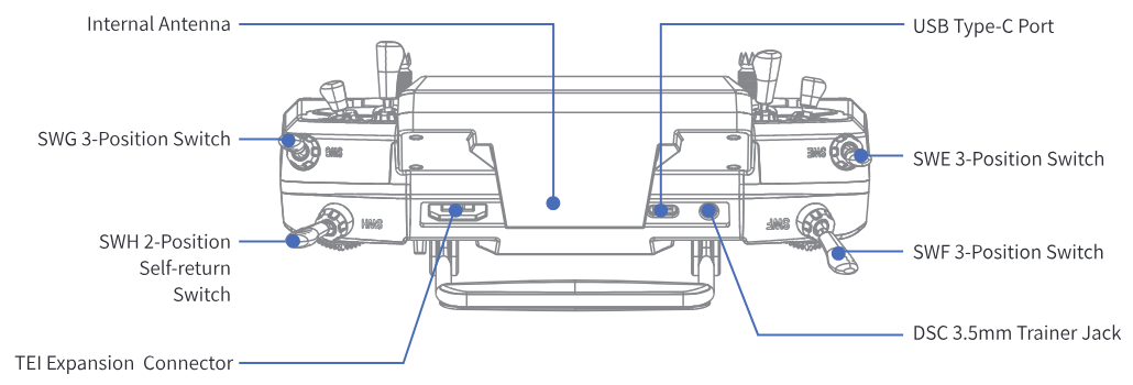
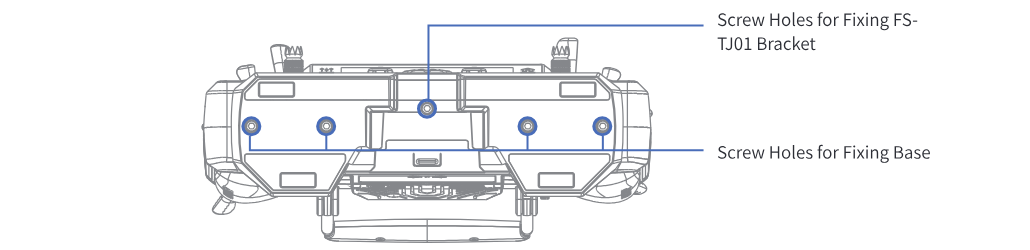
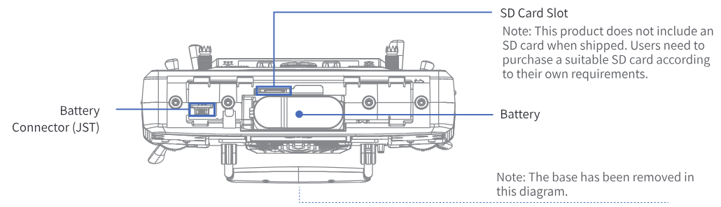
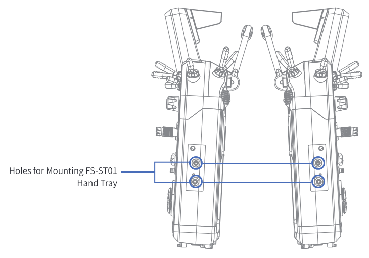
Buttons under left grip and right grip
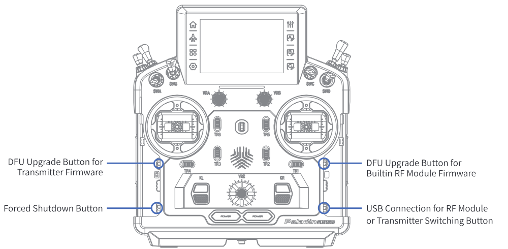
The positions of the 'DFU Upgrade Button for Transmitter Firmware', 'Forced Shutdown Button', 'DFU Upgrade Button for Built-in RF Module Firmware' and 'USB Connection for RF Module or Transmitter Switching Button' are shown in the figure above, you need to tear apart the grip to find it. To press the four keys shown above by using a long thin tool.
- Do not use sharp or metal objects to operate the four buttons as shown in the diagram to prevent damage to the internal structure.
Forced Shutdown Button
In case the transmitter can not be powered off by pressing the two Power Switches, please reset the transmitter with this button.
Setup:
- Pull the grip on the left side of the transmitter and find the Forced Shutdown Button under the grip.
- Insert a long, thin tool into the small round hole and press the Forced Shutdown Button located there. The transmitter will turn off immediately after pressing it.
- After resetting, the settings which were set before resetting may be invalid.
3.2.1Transmitter Antenna
PL18 transmitter has two built-in antennas. When the transmitter starts to work, the antennas automatically operate, without additional operations.
- To ensure a good signal do not cover or block the antenna.
3.2.2Stick/Knob/Dial/Switch/Button
The PL18 Ultra features two joysticks (left and right), three knobs (VRA, VRB, and VRC), eight switches (SWA, SWB, SWC, SWD, SWE, SWF, SWG, and SWH), two dials (VRD and VRE), and eight trim buttons (TR1, TR2, TR3, TR4, TR5, TR6, KL, and KR).
- Sticks: They output different values depending on their position and can output continuous signals. They can be used as function controls, as well as switches to turn functions on or off.
- Knobs/Dials: They can perform the same functions as sticks. Some of them can also be used as trim controls, as well as switches to turn functions on or off.
- Switches: There are two-position, three-position and self-return switches. Different values correspond to different positions. They can be used as function controls, as well as switches to turn functions on or off.
- Trim buttons: They output different values when toggled up or down. They can be used as function controls; for detailed information, refer to section 7.8 on Digital Trim.
3.2.3Status LED
Status indicator (LED) is used to indicate the power and working status of the transmitter.
- The LED is off: Indicates that the transmitter is powered off and not in a charging state.
When the transmitter is powered on, the LED can be in two states: flashing or solid on.
- The LED is off: The transmitter is shutting down.
- The LED is flashing in red: Indicates an alarm, such as a sensor alarm trigger, receiver disconnection, or power-on control position alarm.
- The LED is flashing in green: Indicates binding is in progress or PWM converter is being configured.
- The LED is solid on in green: Indicates connection to the receiver.
- The LED is solid on in blue: Indicates no receiver connected or searching for the receiver.
- The LED is solid on in cyan: Indicates the transmitter is powering on.
- The LED is solid on in yellow: Indicates that the RF is not enabled.
When the transmitter is in a powered-on dormancy state and not charging:
- The LED flashes slowly in blue: Indicates the battery level is high.
- The LED flashes slowly in yellow: Indicates the battery level is medium.
- The LED flashes slowly in red: Indicates the battery level is low.
When the transmitter is in dormancy or power-off state and charging: The LED is cyan to indicate fast charging, and orange to indicate slow charging. The LED has 4 individual lights inside.
- The first LED flashes slowly: Indicates the current battery level is less than 25%.
- The first LED is solid on and the second LED is flashing slowly: 25% ≤ current battery level < 50%.
- The first and second LEDs are solid on and the third LED is flashing slowly: 50% ≤ current battery level < 75%.
- The first three LEDs are solid on and the fourth LED is flashing slowly: 75% ≤ current battery level < 99%.
- LED is solid on: The battery is fully charged and the charger is connected.
Note: This function was updated in version 2.2.18.
3.2.4Stick Mode
This system supports four stick modes. As for aircraft models, from channel 1 to channel 4, by default, these four channels are assigned to aileron, elevator, throttle, and rudder. There are four preset modes of the sticks in order to meet the different requirements. You can select a suitable mode among Mode1, Mode2, Mode3 and Mode4. The green frame indicates the currently selected mode, and the default mode is Mode 2. You can select a suitable mode as you desire. Then you need to adjust the gimbals as needed to match the mode. Follow the steps below.
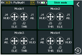
Setup:
- Enter the Model setup interface via (Basic) > Models, then tap the function box next to Stick to enter the stick mode interface.
- Select the mode as you desire. Then click the back arrow to return.
This can also be done after upgrading the firmware or performing a factory reset.
3.2.5Gimbal Assembly Adjustment
Gimbal assembly non self-centering (self-centering) / friction / tension adjustment

As shown above, by adjusting the screws which are located in the screw holes in the back of the transmitter, the gimbal stick can be set to either self-centering or non-self-centering and the friction in case of non self-centering, as well as changing stick tension in case of self-centering (remove the grips to find the relevant screw holes and screws). Screw description is as following:
| ① / ⑤ | Gimbal stick self-centering/non-self-centering adjustment |
| ② / ⑥ | Gimbal stick vertical tension adjustment |
| ③ / ⑦ | Gimbal stick horizontal tension adjustment |
| ④ / ⑧ | Gimbal stick vertical friction adjustment |
- Always perform a stick tension test while turning the screws to ensure stick tension is not too loose or too tight. Overtightening a screw can damage the spring. Loosening a screw too far can cause a spring to fall out in the transmitter and possibly damage the circuitry within. Pay attention to the force when adjusting.
Take right gimbal stick as example.
Non-self-centering to self-centering:
- Use the screwdriver to adjust the screw ① (shown on previous diagram) counterclockwise until the gimbal stick changes to self-centering.
- Adjust the screw ④ counterclockwise to adjust the frictional force.
- If you need to adjust the horizontal centering force or vertical centering force, adjust the corresponding screw ③ or ② accordingly. The force increases clockwise, and decreases counterclockwise.
Self-centering to non self-centering:
- Use the screwdriver to adjust the screw ① clockwise until it is tightened so that the gimbal stick changes to non self-centering.
- Adjust the screw ④ clockwise to strengthen the frictional force.
- If you need to adjust the horizontal centering force, adjust the screw ③ accordingly. The force increases clockwise, and decreases counterclockwise.
Gimbal assembly vertical travel adjustment
For the gimbal assembly of the transmitter, the adjustable range of mechanical travel is from 38° to 54°. Travel can be adjusted as you desire.
- After the adjustment is finished, the stick must be recalibrated.
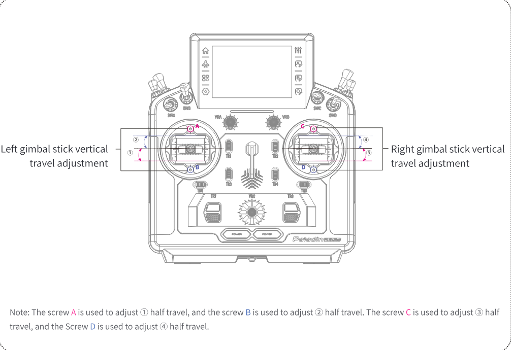
Note: Pay attention to the force when adjusting.
The steps are as follows:
- Use a metric 1.5mm Allen wrench to adjust the corresponding screw in a clockwise direction to increase the travel.
- Adjust the corresponding screw in the counterclockwise direction to decrease the travel.
3.2.6Gimbal Spring Replacement
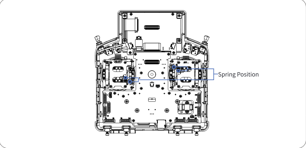
If the gimbal spring is not elastic enough or is damaged, the user can replace it. Please refer to the following steps:
- Remove the 8 screws with an appropriate size Allen wrench after removing the transmitter's grip.
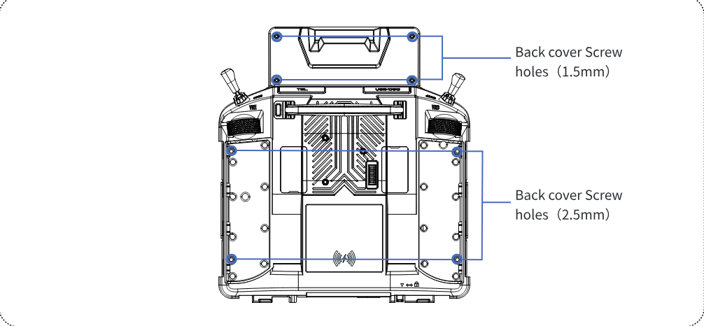
- After removing the back cover of the transmitter, the spring can be replaced with a suitable tool such as tweezers.
3.2.7Installation of Hand Tray
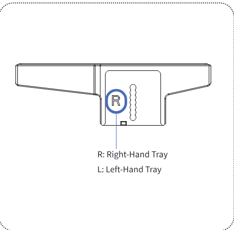
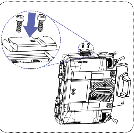
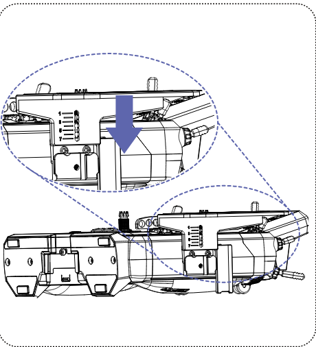
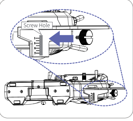
Follow the steps below to install the right hand tray, the left hand tray can be installed by following the same steps.
- According to the letters on the hand tray, you can confirm whether it is the right-hand tray or the left-hand tray (R: right-hand tray, L: left-hand tray).
- After confirming the position of the right-hand tray screw holes, install the screws using a metric 2.5mm Allen wrench.
- Push the right-hand tray in the direction of the arrow as shown until it is not easily dropped.
- Install the screw in the direction of the arrow as shown, and select the appropriate position based on the scale marks on the right-hand tray for installation, until the right-hand rest is securely in place and does not easily become loose.
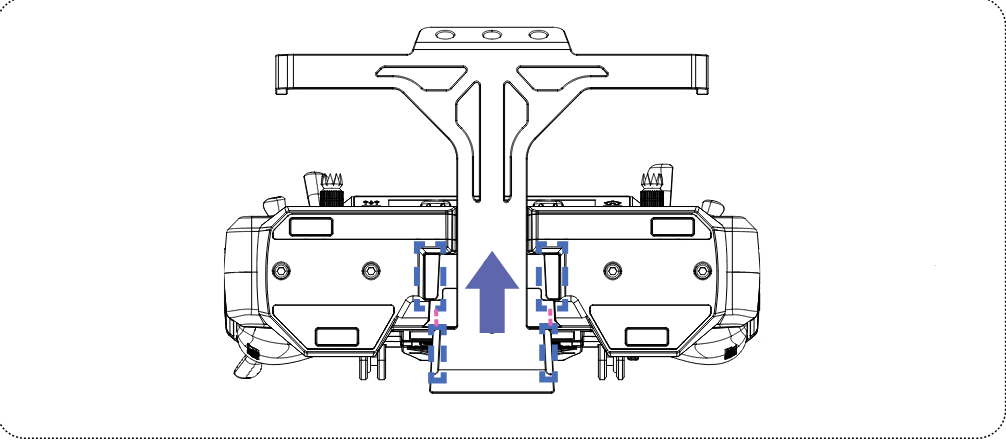
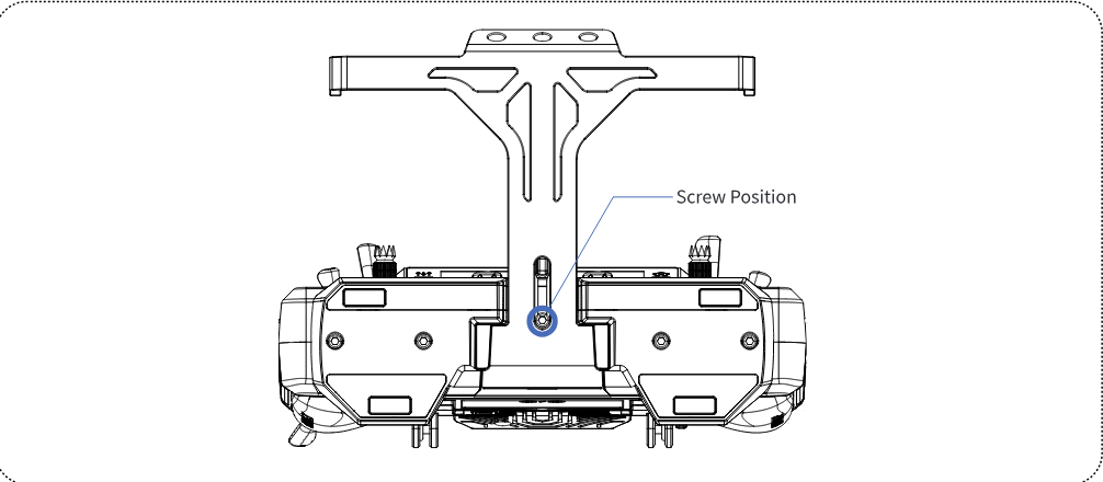
3.2.8Installation of Bracket
Follow the steps below to install the bracket:
- Align the bracket with the slot position of the transmitter base, push the bracket in the direction of the arrow as shown until the bracket snaps into the position properly.
- Use a metric 2.5mm Allen wrench to attach the screw in order to secure the bracket.
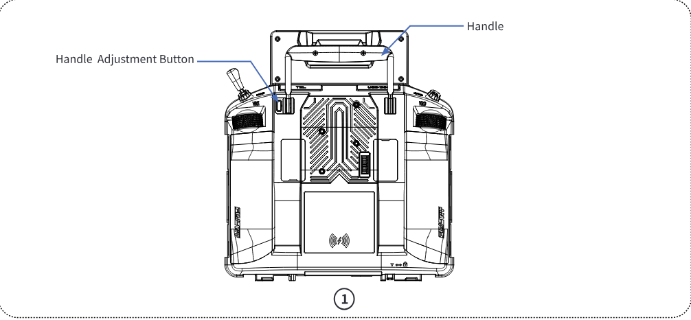
3.2.9Handle Adjustment
The handle can be adjusted according to the two positions in figure 2 and figure 3.
Steps: Press the Handle Adjustment Button and turn the handle. Then, release the handle until it locks into place.
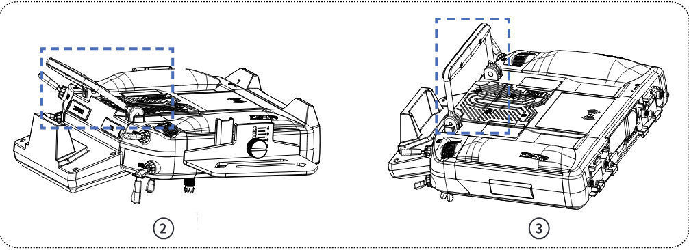
Note: The handle can be adjusted to its maximum or minimum position for easier storage.
3.2.10Power Switches
To prevent false triggering, there are two switches on the lower part of the transmitter. Turn on or turn off the transmitter when both switches are pressed at the same time.
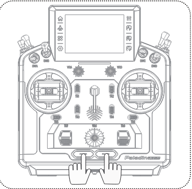
3.2.11Battery Installation
Follow the steps below to install the transmitter battery:
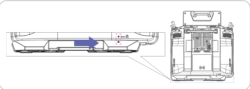
- Remove the 4 screws securing the base.
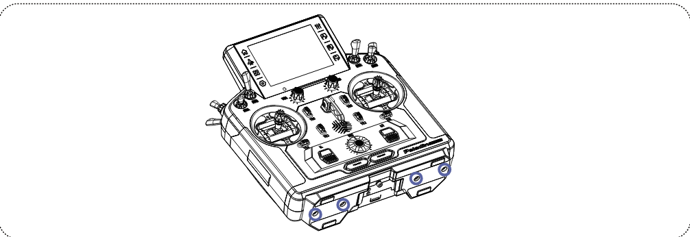
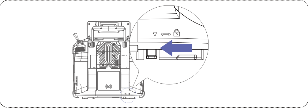
- Push the base in the direction of the arrow as shown until it is removed.
- Install the 1S LiPo battery into the battery compartment and connect the battery wiring to the Battery Connector (JST).
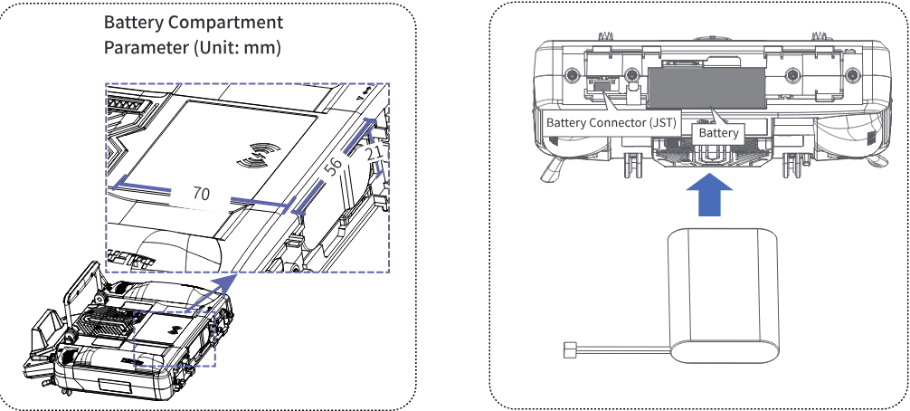
- After aligning the icons on the base and the transmitter, push the base in the direction of the arrow until it is in place. Then, lock the screws and be careful to avoid pinching the battery wiring.
3.2.12Installation About the Center of Gravity Regulator
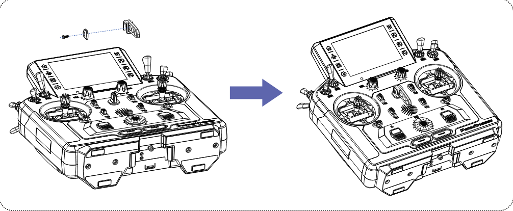
The center of gravity regulator can be installed according to the usage scenario. The steps are as follows:
Align the screw, washer and center of gravity regulator in sequence with the center of the neck strap hook as shown, and secure them at the neck strap hook position.
3.2.13SW-type 3-Position/2-Position Switch Replacement
This transmitter supports replacement of SW-type 3-position/2-position switches, which can change from 3-position switch to 2-position switch or vice versa.
The steps are as below:
- Refer to the previous steps to remove the grips, then remove the eight screws securing the back cover.
- Remove the back cover of the transmitter.
- First, if the cover of the switch is installed, please remove it from the switch. Next, use the appropriate wrench to loosen and remove the sleeve of the switch. Then, carefully release the clip on the switch PCB board. Finally, remove the FPC cable.
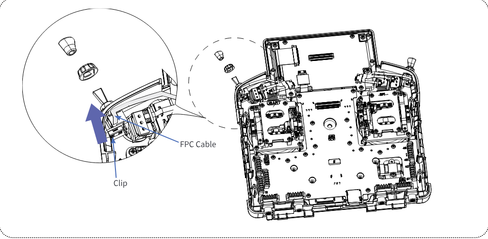
- Take out the switch from the inside of the transmitter.
- Insert the switch to be replaced (with the switch cover removed) into the fixing hole that secures the switch from the inside of the transmitter. Next, release the clip on the switch PCB board and insert the FPC cable connector into the clip. Then, secure the clip and make sure the FPC cable is secured. Finally, use a wrench to tighten the switch sleeve and put on the switch cover.
- Tighten the 8 screws that secure the back cover, and then install the grips one by one.
3.2.14Charging Mode
The transmitter can be charged in two ways: wired charging (USB charging) and wireless charging.
- Wired charging: The USB Type-C cable is connected to the power supply at one end and to the USB Type-C port of the transmitter at the other end.
- Wireless charging: Use the wireless charging dock to charge it (as shown in the figure).
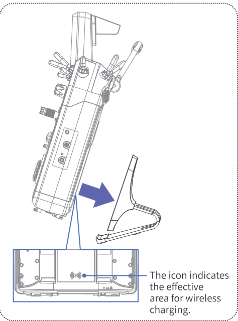
Wired charging supports fast charging up to 18W, and wireless charging supports fast charging up to 12W, both of which will be shown as fast charging mode. If you use a fast charging charger that cannot be recognized by the transmitter, it will be shown as normal charging.
Note: When charging with the power off, tapping the transmitter screen will display charging mode information.
- Please use the USB cable shipped with this transmitter. Improper use may cause damage to the battery and affect its service life.
Notes:
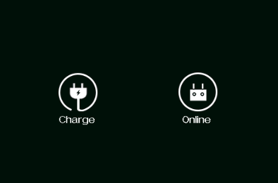
- Before the transmitter is turned on, the transmitter is connected with the computer via the USB Type-C cable. After the transmitter is turned on, a pop-up window will appear, indicating to select the USB function: "Charge" or "Online". If you choose "Charge", the transmitter does not communicate with the computer. If you choose "Online", the transmitter communicates with the computer, that is, FlySky Assistant or simulator software can be accessed.
- By default, wired charging has priority over wireless charging, namely, if the transmitter is connected to both wireless charging and wired charging, wired charging is enabled and wireless charging is disabled.
- Charging in a low temperature, battery capacity and cycle life will reduce.
- Do not store for more than half a year. Charge at least once when storing for half a year, and charge the battery when storing for three months.
- If the transmitter has the battery removed or the battery is in over-discharge protection, the transmitter cannot be turned on by connecting the power supply via the USB Type-C cable; it can be powered on by re-installing the battery or when the battery is charged to a usable state.
3.3Receiver Overview (Take FTr8B as an example)
3.3.1Receiver Overview
![FTr8B receiver from above and its two connector rows with the numbered parts [1] to [16]](/manuals/pl18-ultra/receiver.png)
| [1] | CH1 |
| [2]–[4] | CH2–CH4 |
| [5] | CH5 (NPD) |
| [6] | CH6 (NPC) |
| [7] | CH7 (NPB) |
| [8] | CH8 (NPA) |
| [9] | BVD/VCC (battery voltage detection / power supply interface) |
| [10] | S (signal pin) |
| [11] | + (power anode) |
| [12] | − (power cathode) |
| [13] | LED |
| [14] | BIND button |
| [15] | Antenna 1 (the right antenna) |
| [16] | Antenna 2 (the left antenna) |
3.3.2Status Indicator
The LED (status indicator) is used to indicate the power and operating status of the receiver.
- Off: The receiver power is not connected.
- Solid on in red: The receiver is connected to the power supply and is working properly.
- Fast flashing: The receiver is in binding mode.
- Slow flashing: The transmitter which the receiver is bound to is powered off, the signal is lost or the receiver firmware is updating.
- Three-flash-one-off: The receiver has entered forced firmware update mode.
4Pre-operation Setup
Follow the instructions and guidelines in this chapter before use.
4.1Receiver And Servo Installation
Make sure that the receiver is mounted in an appropriate location within the model, to ensure a stable signal, maximum range and to mitigate external interference, follow these guidelines:
Pay attention to the following when installing the receiver:
- Make sure the receiver is not installed near ESCs or other sources of electrical noise.
- Keep the receiver's antenna away from conductive materials such as carbon or metal. To ensure normal function make sure there is a gap of at least 1cm between the antenna and the conductive material.
- To prevent damage do not power on the receiver during installation.
5Operation Guidelines
Follow these guidelines to use the transmitter and the receiver.
5.1Power-On
When the transmitter is powered on for the first time, the power-on wizard interface will appear. Finish the settings on Stick Mode (ST Mode), Stick Calibration (ST Cali.) and Update RF according to the interface prompts, and then click Start using. Tap the top left corner of the reminder screen to change the language.
The transmitter will also enter the power-on wizard function after upgrading the firmware via the TX firmware update function or after resetting via the Factory reset function.
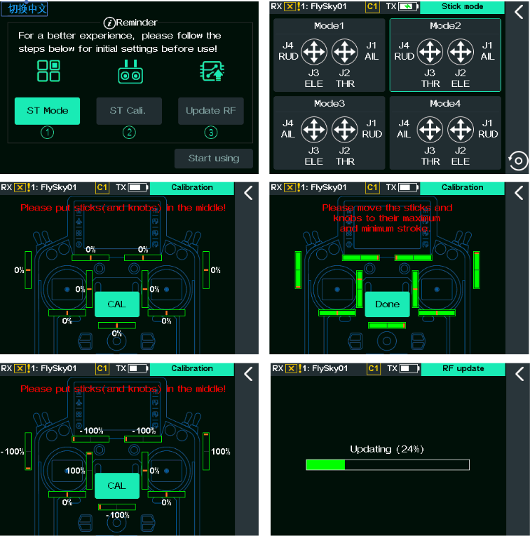
In addition to this, please follow the steps below to power on the transmitter:
- Check to make sure that the battery is fully charged.
- Press and hold the two Power Switches at the same time until the screen turns on.
- Follow the pop-up prompts accordingly to power on the transmitter.
- Whether to turn on the transmit function. If RF is not required for this power-up, the transmit function can be switched off.
- Whether the switch is in a safe position. (A red background on a control indicates that the position needs to be adjusted.) Check the position of the control according to the prompts and move it to the correct position.
- Whether the current model has failsafe set. To turn off the failsafe setting reminder when powering on the device, click Ignore or turn off "Startup reminder failsafe is not set" in General.
- The system is now active, be cautious to not cause damage or personal injury.
- If the SWA/SWB/SWC/SWD/SWE/SWF/SWG/SWH switches are not at their safe positions and the throttle stick is not at its low position when the transmitter is powered on, a prompt will appear to remind you to put these switches and throttle stick to their proper positions. It is recommended to follow the reminder to put them to their proper positions. The transmitter will launch. If you click Go to launch the transmitter without putting them to their proper positions, this may lead to danger.
Note: This function was updated in version 2.2.18.
5.2Binding
The transmitter and the receiver have been pre-bound at the factory. If you need to rebind or bind a new receiver follow the steps below. The Flysky AFHDS 3 receivers consist of classic edition receivers and enhanced edition receivers. The bind method is slightly different between these two editions.
Note: The Flysky AFHDS 3 classic edition receiver models include FTr10, FGr4, FGr4s, FGr4P, FTr4, and FTr16S. Other Flysky AFHDS 3 receivers are considered enhanced edition receivers.
- Power off the servo while the transmitter and the receiver are binding. Otherwise, it may lead to danger.
- After the binding process is completed, power off the receiver, then power on the receiver and check to make sure that the transmitter and the receiver have bound successfully.
To enter the Bind setting interface via (Basic) > RX setting.
The binding interface of enhanced edition receiver
Binding 1 receiver:
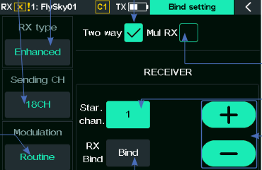
- RX type: Displays the RX type; click to switch the RX type: [Enhanced] or [Classic].
- Sending CH: Displays the number of output channels. Click to switch the number of output channels: [18CH], [12CH], [8CH], or [4CH (Fast)]. Select a receiver with the corresponding number of channels based on the transmitter's channel count. If the receiver has too few channels, it may affect the functionality of the transmitter. If it has too many, it will waste channel resources. For example, if you need to use 8 or fewer channels (such as with the FTr8B, which only has 8 PWM channel outputs), the transmitter can be set to 8 channels. For dual-receiver mode or 18CH expansion (via PWM converter), the transmitter's channel count should be set to 18 channels.
- Modulation: Displays the modulation mode; click to switch: [Routine] or [Antijamming priority]. For more details, see the table following.
- Two way: To set the transmitter and receiver to connect in one-way or two-way mode. A checkmark (√) indicates a two-way connection. Note: When one-way communication is selected, there will be no telemetry feedback to the transmitter.
- Mul RX: To set multiple receivers or not. If a mark (√) appears, multiple RXs can be bound; otherwise, only one receiver can be bound.
- Star. chan.: Receiver starting channel. Tap to change the value. Click + to increase the value, and − to decrease it.
- Bind: Click Bind to put the transmitter into binding mode. After that, a menu will pop up, showing the binding process.
Binding 2 receivers (1 primary, 1 secondary):
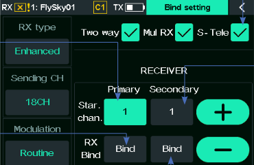
- S-Tele: Check or uncheck the S-Tele option. It is checked by default, allowing for the binding of only one secondary receiver, which returns only its own information back to the transmitter.
- Primary Star. chan.: To set the starting channel of the primary receiver, the range is from 1 to 18. If the [Sending CH] is set to 4 CH, the starting channel setting range for the primary/secondary receiver is 1 to 4.
- Secondary Star. chan.: To set the starting channel of the secondary receiver, the range is from 1 to 18. For example, to achieve dual-receiver 18-channel output, you can set it up as follows: take the primary receiver as FTr12B and the secondary receiver as FTr8B. The starting channel of the secondary receiver should be set to 13. In this way, channel 1 of the secondary receiver will output the transmitter's channel 13, and channel 6 will output the transmitter's channel 18.
- Primary Bind: To bind the transmitter with the primary receiver. Click it to put the transmitter into binding mode. "Connected" will be displayed once the binding is finished.
- Secondary Bind: To bind the transmitter with the secondary receiver. Click it to put the transmitter into binding mode.
Binding 2 receivers (1 primary, multiple secondaries):
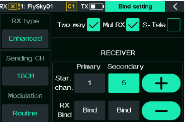
Here are the introductions of [Routine] and [Antijamming priority].
| Modulation | Key features | Application scenarios |
|---|---|---|
| Routine | In [Routine] mode, the system provides a balanced performance, offering moderate anti-interference capabilities and a moderate maximum control distance. | The [Routine] mode is suitable for most non-demanding scenarios, such as casual weekend use in parks. These environments typically feature open spaces with occasional WiFi signals or 2.4GHz devices (but not heavy interference). In such cases, neither extreme control range nor high-intensity interference resistance is required. |
| Antijamming priority | In [Antijamming priority] mode, the system uses high-density data packets. This keeps communication reliable even with lots of interference and packet loss. But it doesn't help with distance in low-interference situations. | This mode prioritizes stable connectivity in complex electromagnetic environments. By compromising maximum operational range, it ensures reliable performance in high-interference scenarios such as RC model exhibitions or crowded flying zones at events. |
Binding multiple receivers: When you check "Mul RX" and do not check "S-Tele", you can bind multiple receivers. In this case:
- Primary receiver: In this mode, the RX ID is not transmitted during both binding and communication. Please note: If binding multiple receivers, do not power on the primary receivers simultaneously, as this may cause the transmitter's telemetry data to conflict by switching between devices, resulting in display errors. Therefore, bind only one primary receiver. Any additional receivers should be bound through the secondary receiver entry. If multiple receivers are bound in this mode across different models, all receivers bound this way under these models can be controlled by the same transmitter. Therefore, ensure only the receiver corresponding to the current model is powered on during use.
- Secondary receiver: In this mode, devices bound through the secondary receiver interface do not have telemetry functionality. Before binding a secondary receiver, the starting channel and interface protocol must be set in advance. These settings can only be configured before the binding process and cannot be changed after successful binding.
Take FTr8B receiver as an example.
Steps for binding one receiver:
- Tap (Basic) > RX setting > Bind setting to enter the bind setting interface (the RX type is Enhanced by default).
- Based on practical application requirements: Enable/disable two-way communication — check the box to enable two-way communication (uncheck for one-way). Set Sending CH (output channel quantity) — click the function box below "Sending CH", then select "Yes" in the pop-up window to toggle options. Set modulation mode — click the function box below "Modulation", then select "Yes" in the pop-up window to toggle options. Set starting channel — click the function box to the right of "Star. Chan.", then use "+" / "−" to adjust the value.
- Tap Bind, and the transmitter will enter the binding state.
- Press and hold the BIND button on the receiver while powering it on; the LED of the receiver will flash rapidly to indicate that it has entered the binding state.
- The binding process is finished when the LED of the receiver stops flashing and is solid on. When the transmitter enters the binding state in one-way mode, after the receiver LED becomes slow flashing, put the transmitter out of the binding state by tapping the back arrow. At this time, the receiver LED is solid on indicating the binding is successful.
- Confirm that the transmitter and the receiver are operating correctly; if not, repeat the steps above.
Steps for binding two receivers:
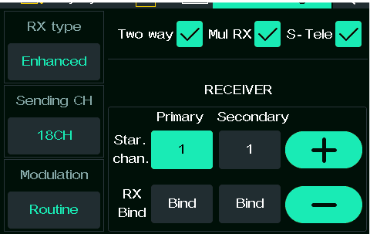
- Two way, Mul RX and S-Tele are checked (if Mul RX is ticked, S-Tele will be checked by default).
- To bind the primary receiver, follow these steps: Refer to step 2 of the "binding a receiver" procedure to configure Sending CH and modulation mode. Set the starting channel. Default: 1. You can set the appropriate starting channel as needed. For example, if it is set to 1, the primary receiver's CH1 will correspond to the transmitter's CH1. Click Bind, the transmitter enters the binding state, and then put the primary receiver into the binding state to finish the binding.
- To bind the secondary receiver, follow these steps: Set the starting channel. Default: 1. You can set the appropriate starting channel as needed. For example, if it is set to 7, the secondary receiver's CH1 will correspond to the transmitter's CH7. Click Bind, the transmitter enters the binding state, and then put the secondary receiver into the binding state to finish the binding.
- Confirm that the transmitter and the receiver are operating correctly; if not, repeat the steps above.
Steps for binding more than two receivers:
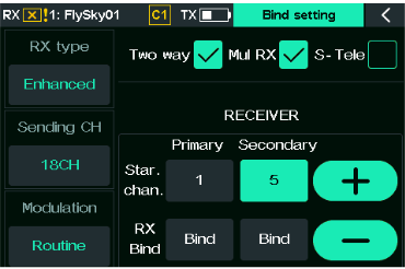
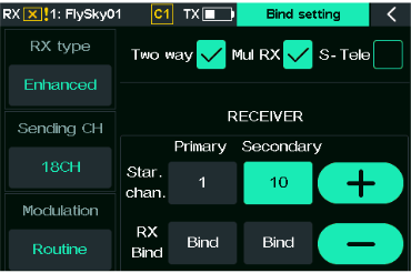
- Tick the boxes for Two way and Mul RX, but do not tick the box for S-Tele.
- Refer to step 2 of the "binding two receivers" procedure to finish the binding for the primary receiver.
- To bind the secondary receiver 1, you must first set the interface protocol and starting channel for this receiver before beginning the binding process. Note that these settings cannot be changed after the binding is complete. Follow these steps: Configure the Newport interface protocol via Custom Interface Protocol. Refer to step 3 of the "binding two receivers" procedure to set the starting channel. Complete binding with secondary receiver 1.
- And so on, bind more secondary receivers with the transmitter.
- Confirm that the transmitter and the receiver are operating correctly; if not, repeat the steps above.
Notes:
- The binding method may vary with different receivers. For specific binding methods, please visit the official website of FLYSKY for receiver instructions or other relevant information.
- After the transmitter and receiver establish stable two-way communication, a pop-up window will appear when the receiver is identified as a compatible receiver of a non-FlySky authorized third-party brand. Meanwhile, the radio frequency will be interrupted.
The binding interface of classic edition receiver
The classic version receiver supports 18-channel communication, featuring both one-way and two-way binding, and allows binding with a single receiver.
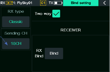
- Sending CH: Displays the number of output channels. Click to switch the number of output channels: [18CH] or [10CH].
Setup:
- Tap (Basic) > RX setting > Bind setting to enter the bind setting interface.
- Set RX type: Click the function box below "RX type", then select "Yes" in the pop-up window to set to Classic.
- Set Sending CH: Refer to step 2 of the "binding a receiver" procedure to configure Sending CH.
- Tap Bind, and the transmitter will enter the binding state.
- Insert the bind cable into the receiver's BIND interface, and plug the power cable into any other port. At this time, the LED of the receiver will flash rapidly to indicate that it has entered the binding state.
- Remove the binding cable and power cord from the receiver when the LED of the receiver stops flashing and is solid on. When the transmitter enters the binding state in one-way mode, after the receiver LED becomes slow flashing, put the transmitter out of the binding state by tapping the back arrow.
- Reconnect the power cord to the receiver. The receiver LED is solid on indicating the binding is successful.
- Check to make sure the transmitter and the receiver are working normally, repeat the steps above if any problems arise.
Note: This function was updated in version 2.2.18.
5.3Pre-operation Checks
Always perform the following steps before each operation:
- Inspect the entire system to make sure that everything is working as expected.
- Perform a range test as described in the 14.6 Range Test section of the user manual.
- Do not use the model if there are any abnormal behaviors during the test.
- Do not exceed the maximum rated range during use.
- Interference from other transmitting devices may reduce signal quality.
5.4Power-Off
Follow these steps to power off the system:
- Power off the receiver.
- Press and hold both Power Switches on the transmitter. The screen will then dim, displaying the prompt 'Shut down... please waiting for!' After that, the screen turns off, indicating that the transmitter has been powered off.
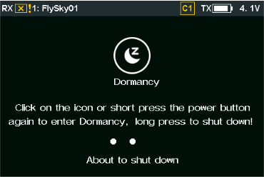

Note: Pressing both power switches on the transmitter will pop up a prompt displaying the shutdown duration and the dormancy mode icon. For more information on the dormancy function, refer to section 14.2.5 Dormancy.
- To avoid any risk of losing control of the model, always power off the receiver before powering off the transmitter.
Note: This function was updated in version 2.2.18.
5.5Low Voltage Alarm (Pop-up/Audible)
When the transmitter is powered on and not in dormancy mode, if the system detects low voltage, an audible alarm will sound and a pop-up alarm will appear with relevant information, as described below.
- When the system detects the voltage below 3.5V, 'Transmitter voltage low!' will activate in pop-up alarm and audible alarm. In this status, both the pop-up alarm and the audible alarm prompt once.
- When the system detects the voltage below 3.46V, a screen pop-up will display 'Transmitter voltage very low', accompanied by an audible alarm that repeats every 20 minutes.
- When the system detects the voltage below 3.42V, a screen pop-up will display 'Transmitter Voltage Low, please charge' accompanied by an audible alarm that repeats once every 10 minutes.
- If the transmitter's voltage drops below 3.2V, the system will automatically shut down, and a pop-up message 'Transmitter voltage low, automatic shutdown!' will appear on the screen, accompanied by an audible alarm.
Notes:
- To turn off the audible alarm, you can go to (System) > General > Sound to disable the alarm sound.
- If the transmitter is in the process of binding, powering on, powering off, updating RF module firmware, or other operations, no low voltage alarm will be given.
5.6Manually Entering Dormancy Mode
The system supports manually entering dormancy mode.
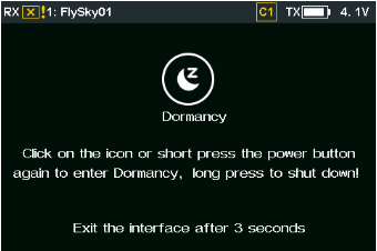
Setup:
- Press both power switches on the transmitter simultaneously until the prompt "Click on the icon or short press the power button again to enter Dormancy, long press to shut down!" appears, then release the power switches.
- Tap the Dormancy icon or press both power switches again (and release within 3 seconds), and the transmitter will enter dormancy mode.
Note: If the transmitter is communicating normally with the receiver at this time, clicking the Dormancy icon will prompt a dialog box asking, "This action will cause the receiver to lose control, confirm?"
Here is an introduction to the transmitter's dormancy mode status and how to exit dormancy mode.
Dormancy state
- Control state: Stick, switch, dial, trim, and knob operations are ineffective.
- RF state: RF not working: the built-in RF module is off, and there is no signal or power on the external RF module connector.
Notes:
- In dormancy mode, devices connected to the data connectors do not operate, thereby reducing power consumption.
- After the transmitter enters dormancy mode, the transmitter LED is in a slow flashing state. For details, refer to 3.2.3 Status Indicator.
- It is recommended to use dormancy mode during training or competition instead of turning off the transmitter's power.
Exiting dormancy mode
To wake the transmitter from dormancy mode.
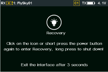
Setup:
- Tap the screen or press both power switches on the transmitter simultaneously until the prompt "Click on the icon or short press the power button again to enter Recovery, long press to shut down!" appears, then release the power switches.
- Tap the Recovery icon or press the power switches (release within 3 seconds), and the transmitter will exit dormancy mode.
Note: If you press and hold both power switches (without releasing within 3 seconds), the transmitter will power off.
The transmitter will automatically exit dormancy mode under certain special circumstances.
- When the transmitter is in a low battery state, it will automatically power off.
- After staying in dormancy mode for 6 hours, the transmitter will automatically power off, which also exits dormancy mode.
Note: For automatic dormancy settings, please refer to section 14.2.5 Dormancy.
Note: This function was updated in version 2.2.18.
6Main Interface
This is an introduction to the transmitter's main interface.
6.1Main Interface Overview
The main interface primarily shows information related to the model, such as sensor data and function status, and offers quick access to these features. By tapping on the relevant areas of the main interface and the right main interfaces, you can quickly access the corresponding functional interfaces.
Left and right shortcuts
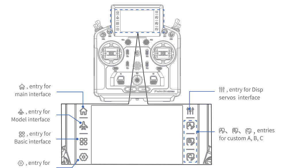
- Left shortcut: entry for the main interface, entry for the Model interface, entry for the Basic interface, entry for the System interface.
- Right shortcut: entry for the Disp servos interface, entries for custom A, B, C.
Note: Custom A, Custom B and Custom C of the right shortcut are not assigned by default and do not respond when touching. After setting the specific functions, you can use the shortcut here to access the corresponding function quickly.
Main interface
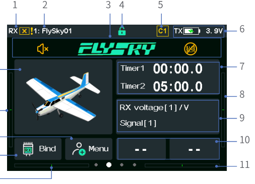
- Display signal strength / RX is not connected / RF is disabled.
- Model name.
- Status column. Some function icons are displayed in this area if the corresponding functions are activated, such as Vibration, Sound, Logic switches and Fuel alarm. Different function icons will appear in this area in various models: Airplane: Airbrake, Butterfly, Throttle cut and Idle up. Gliders: Airbrake and Butterfly. Helicopters: Throttle cut, Idle up and Throttle hold. Multicopters: Throttle hold. Cars: ABS.
- Lock icon. Tap the icon to lock the screen; long press it to unlock.
- Current condition.
- Transmitter power display.
- Timer value display; Timer 1 entry.
- TR2 trim value display.
- Sensor display; Sensor entry. RX voltage [1]: displays the low voltage voice alarm value. Signal [1]: displays the signal strength value of the primary receiver. When there is no primary receiver, it displays the signal strength value of the secondary receiver. Note: No value is displayed with one-way communication or when the external RF protocol is PPM/CRSF/CRSF2.
- Custom sensor display 1/2; Sensor display 1 / Sensor display 2 entry. Customize the display of sensor data: tap to enter the Sensor display 1 settings interface, and then tap the appropriate option. Click the back arrow to return.
- TR1 trim value display.
- TR4 trim value display.
- Bind setting entry. Note: This area is not displayed when the RF is set to PPM, CRSF, or CRSF2.
- Custom menu entry.
- TR3 trim value display.
- Display current model image; and entry for Model select.
![Sensor display 1 settings with the options None and TX voltage [0]](/manuals/pl18-ultra/screen-sensor-display.png)
Model alarm pop-up notification
![Alarm pop-up on the main interface listing TX voltage [0] alarm, CH3 (THRO) alarm and J2 alarm with an Exit button](/manuals/pl18-ultra/screen-alarm-popup.png)
Note: This pop-up window appears for all alarms under the Model alarm function, except Power on alarm and Telemetry loss alarm. Tap the pop-up window to view up to 3 alarm messages. Tap EXIT to close the window.
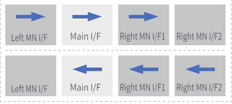
Four dots indicate four pages: The white dot indicates the current page, and the gray dots represent the other pages. To enter the other pages, swipe the screen left or right.
Right main interface 1
![Right main interface 1 with four gauges: CH3 (THRO), TX voltage [0], Temperature [3] and Knob VRA, each with min and max values](/manuals/pl18-ultra/screen-right-main-1.png)
The four areas display real-time information and statistical values for record objects 1 to 4 and are the entries to Data record.
Note: The record object can be set to 'Sensor data', 'Output channel' or 'Stick or knob'.
After setting the recording object:
![Right main interface 1 after setting the recording objects: TX voltage [0], CH2 (ELEV), J3 and Temperature [3]](/manuals/pl18-ultra/screen-right-main-1b.png)
- Each gauge displays the real-time value.
- The line below displays real-time maximum, minimum and average information of the recording object within the recording duration.
Right main interface 2
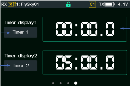
- Timer display 1 / Timer display 2: entry to the timer display.
- Display time information. Start / Stop: click this area to start (or pause) timing. Reset: press and hold this area for 1 second to reset the timer.
Left main interface
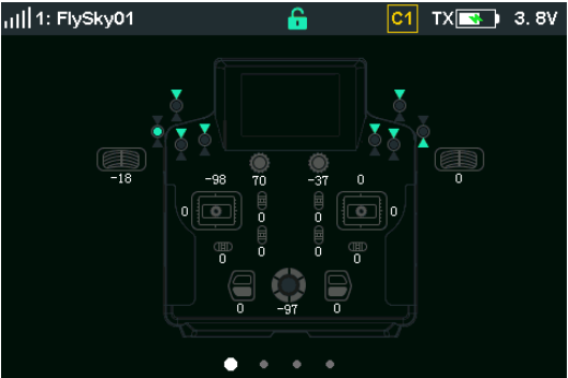
- For switches: Displays the current physical position of the switch.
- For knobs/dials: Displays the current value of the knob.
- For sticks: Displays the current value of the stick.
- For trims: Displays the current value of the trim.
Note: This function was updated in version 2.2.18.
6.1.1Status Bar (Top)
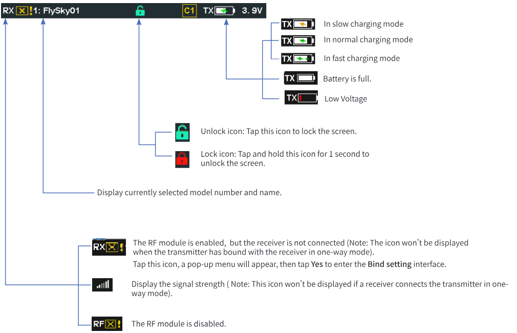
- TX battery icon: shows slow charging mode, normal charging mode, fast charging mode, battery full, or low voltage.
- Unlock icon: Tap this icon to lock the screen. Lock icon: Tap and hold this icon for 1 second to unlock the screen.
- Displays the currently selected model number and name.
- RX with a cross: The RF module is enabled, but the receiver is not connected (Note: The icon won't be displayed when the transmitter has bound with the receiver in one-way mode). Tap this icon, a pop-up menu will appear, then tap Yes to enter the Bind setting interface.
- Signal bars: Displays the signal strength (Note: This icon won't be displayed if a receiver connects the transmitter in one-way mode).
- RF with a cross: The RF module is disabled.
6.2Interface
This section is a quick introduction to the icons of the interface.
6.2.1Function Icons
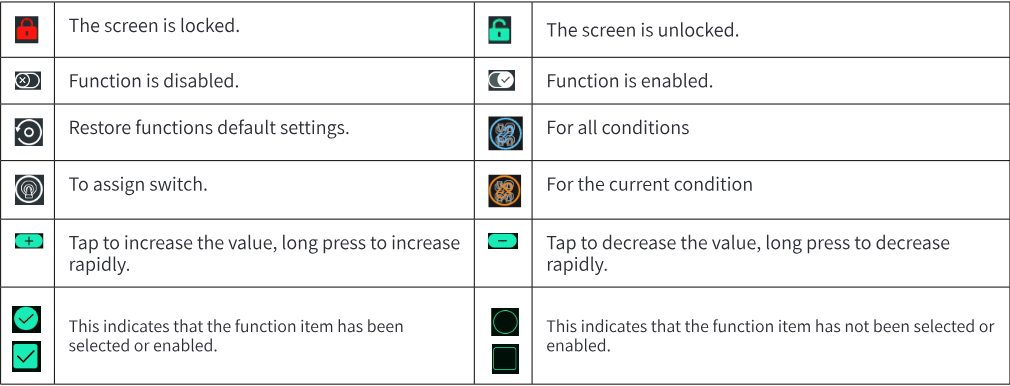
| Red lock | The screen is locked. |
| Green lock | The screen is unlocked. |
| Toggle off | Function is disabled. |
| Toggle on | Function is enabled. |
| Reset icon | Restore the function's default settings. |
| Switch icon | To assign a switch. |
| Blue conditions icon | For all conditions. |
| Orange conditions icon | For the current condition. |
| + | Tap to increase the value, long press to increase rapidly. |
| − | Tap to decrease the value, long press to decrease rapidly. |
| Green checkmark | This indicates that the function item has been selected or enabled. |
| Empty box | This indicates that the function item has not been selected or enabled. |