
1Safety
1.1Safety Symbols
Pay close attention to the following symbols and their meanings. Failure to follow these warnings could cause damage, injury or death.
| Danger | Not following these instructions may lead to serious injuries or death. |
| Warning | Not following these instructions may lead to major injuries. |
| Attention | Not following these instructions may lead to minor injuries. |
1.2Safety Guide
Prohibited:
- Do not use the product at night or in bad weather like rain or thunderstorm. It can cause erratic operation or loss of control.
- Do not use the product when visibility is limited.
- Do not use the product on rain or snow days. Any exposure to moisture (water or snow) may cause erratic operation or loss of control.
- Interference may cause loss of control. To ensure the safety of you and others, do not operate in the following places: near any site where other radio control activity may occur; near power lines or communication broadcasting antennas; near people or roads; on any body of water when passenger boats are present.
- Do not use this product when you are tired, uncomfortable, or under the influence of alcohol or drugs. Doing so may cause serious injury to yourself or others.
- The 2.4GHz radio band is limited to line of sight. Always keep your model in sight as a large object can block the RF signal and lead to loss of control.
- Never grip the transmitter antenna during operation. It significantly degrades signal quality and strength and may cause loss of control.
- Do not touch any part of the model that may generate heat during operation, or immediately after use. The engine, motor or speed control may be very hot and can cause serious burns.
Mandatory:
- Misuse of this product may lead to serious injury or death. To ensure the safety of you and your equipment, read this manual and follow the instructions.
- Make sure the product is properly installed in your model. Failure to do so may result in serious injury.
- Make sure to disconnect the receiver battery before turning off the transmitter. Failure to do so may lead to unintended operation and cause an accident.
- Ensure that all servos operate in the correct direction. If not, adjust the direction first.
- Make sure the model stays within a certain distance. Otherwise, it would cause loss of control.
2Introduction
This product uses the 2.4GHz Third Generation AFHDS 3 protocol. The Noble NB4+ transmitter and FGr4B receiver constitute a system, compatible with model cars, boats and other models. Additionally, it supports USB simulator functionality (enabled by default).
2.1System Features
AFHDS 3 (third-generation automatic frequency hopping digital system) is a newly developed digital wireless system. It is compatible with single antenna bidirectional real-time data packet transmission and data stream transmission. With the advantages that come with the WS2A wireless system and the new 2.4GHz chip, the system can dynamically set: number of channels, channel resolution, range, anti-interference requirements and latency to meet the needs of different users.
| Compatible with Unidirectional/Bidirectional Real-time Data Transmission | The system supports one-way and two-way connections. When the transmitter is working in one-way transmission way, the receiver can receive data from the transmitter. When the transmitter is working in two-way transmission way, the receiver can receive data from the transmitter and the transmitter can also receive data from the receiver, as well as the information from the temperature and speed sensor modules. This gives better control over the models and obtains information on its current status, so as to make model control more secure. |
| Uncorrected Data Transmission | The independent uncorrected data transmission module is built into the RF system; it can send many different types of data including flight control data. |
| Intelligent RF configuration | Depending on hardware, certification, the amount of data to be transmitted, anti-interference, latency and distance requirements, the system intelligently adapts the corresponding RF configuration to meet the requirements of the user. |
| Multi-channel Frequency Hopping | This system's bandwidth ranges from 2.402GHz to 2.480GHz. Intelligent RF configuration according to the needs of RF configuration, through the different RF configuration, different power-on time, different frequency hopping law and different use of frequency points to actively avoid the same frequency interference. |
| Unique ID Recognition System | Each transmitter and receiver has its own unique ID. Once the transmitter and receiver have been paired, they will only communicate with each other, preventing other systems accidentally connecting to or interfering with the system's operation. |
| Low Power Consumption | The system is built using highly sensitive low power consumption components, maintaining high receiver sensitivity, while consuming as little as one tenth the power of a standard FM system, dramatically extending battery life. |
2.2Transmitter Overview
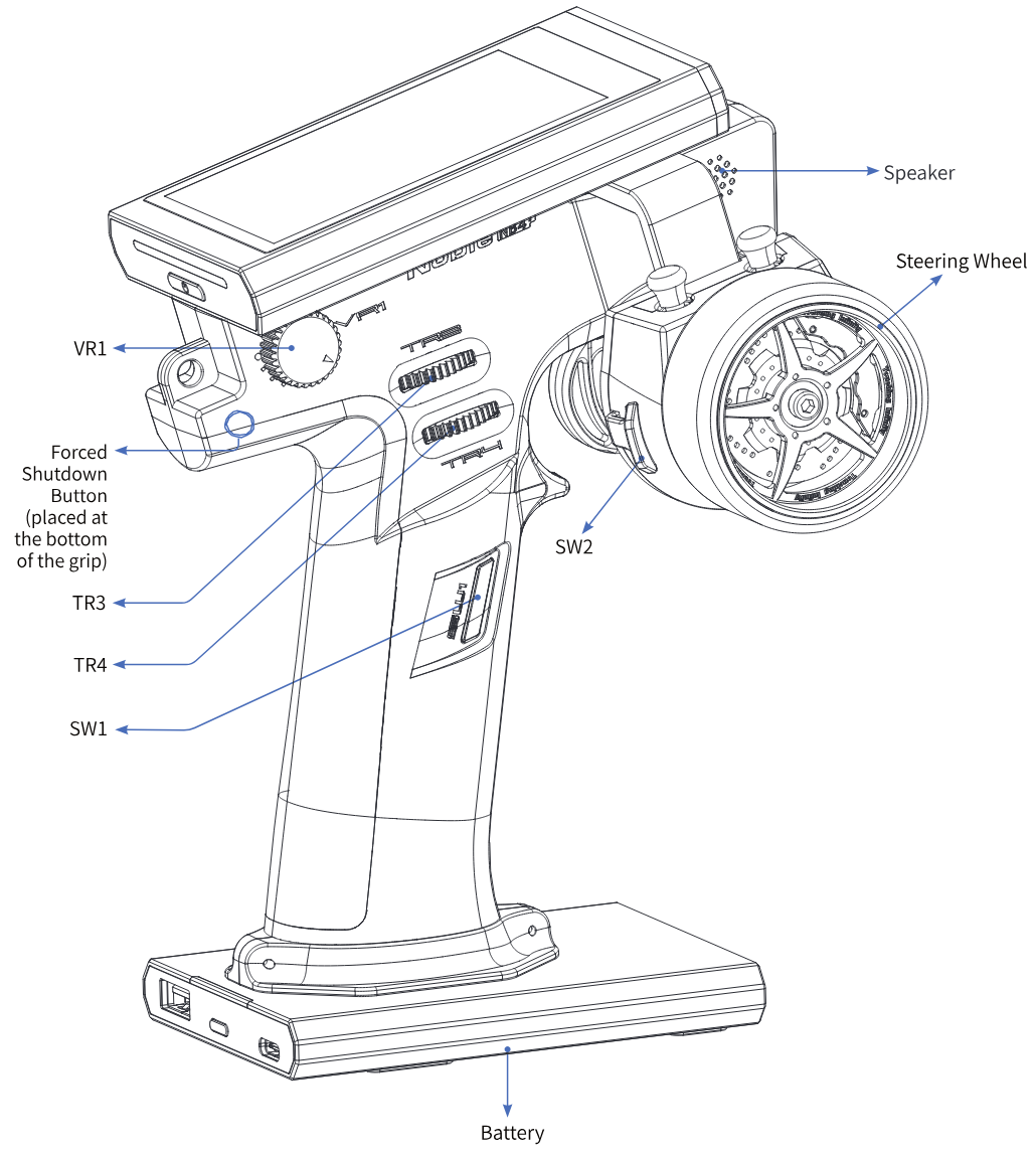
Note: If you can't shut down the transmitter properly, please shut down the transmitter by pressing the forced shutdown button on the transmitter. Operation: pull the hand grip placed at the top of the transmitter's grip or take off the whole handle grip. Use a relatively slender tool, insert the tool into the round hole on the right side of the grip, and press the forced switch button in the round hole. After pressing the button, the transmitter will be shut down immediately.
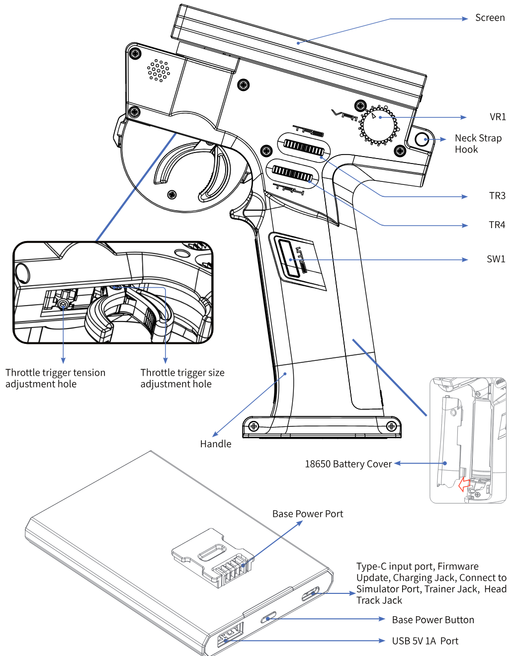
Base power button: Press for a short time to charge the battery at the transmitter handle and to charge external devices. Press 2 seconds to turn off the output of the power supply.
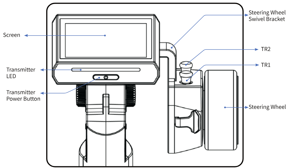
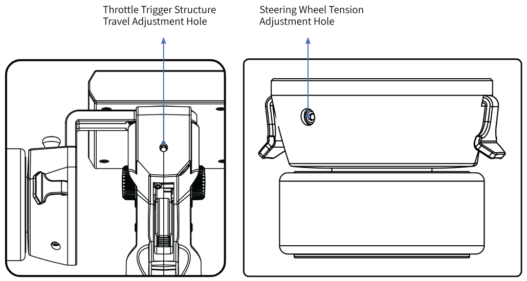
2.3Receiver Overview (FGr4B)
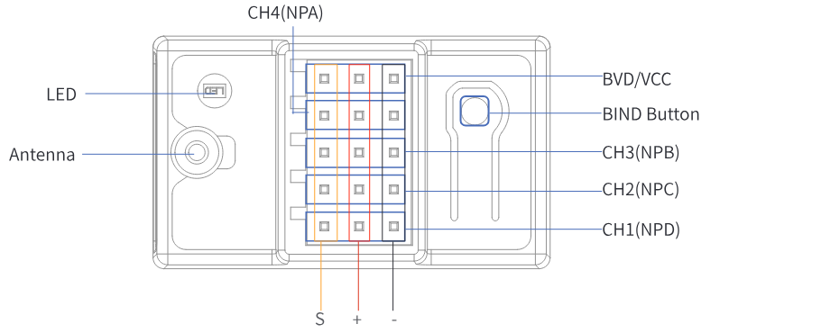
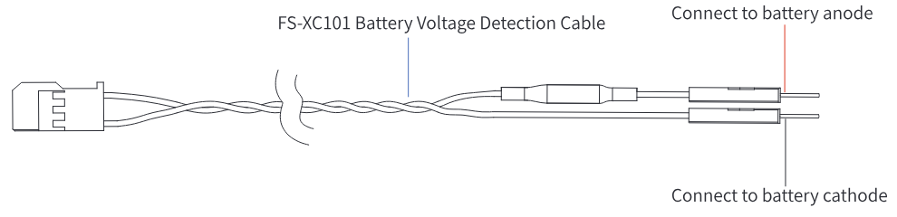
2.3.1Status Indicator
The status indicator is used to indicate the power and working status of the receiver.
- Off: The power is not connected.
- Solid on in red: The receiver is powered on and working.
- Flashing quickly: The receiver is binding.
- Flashing slowly: The bound transmitter is off or signal is lost.
- Three-flash-one-off state: The receiver enters forced firmware update.
3Getting Started
Before operation, install the battery and connect the system as instructed below.
3.1Transmitter Battery Installation
- Only use included batteries.
- Do not open, disassemble, or attempt to repair the battery.
- Do not crush/puncture the battery, or short the external contacts.
- Do not expose to excessive heat or liquids.
- Do not drop the battery or expose to strong shocks or vibrations.
- Always store the battery in a cool, dry place.
- Do not use the battery if damaged.
The Noble NB4+ has 2 batteries, one located in the handle and one in the removable base.
To attach the base:
- Line up the base so that the transmitter handle has a slight overhang on the back.
- Carefully insert the base contacts into the hole in the bottom of the handle.
- Hold the handle firmly and pull the battery backwards. When it is secure you should hear a click.
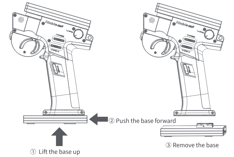
Steps for replacing the built-in battery of the handle:
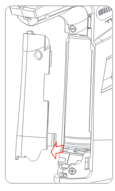
- Remove the grip first, and then remove the handle battery cover (18650 battery cover).
- Remove the 18650 battery to be replaced, align the negative end of the fully charged 18650 battery with the end of the battery compartment with spring, press the spring and install the battery.
- Close the handle battery cover (18650 battery cover), install the grip, switch it on, and test whether the transmitter works normally.
Notes:
- Before replacing the handle built-in battery, make sure the transmitter is powered off and disconnected!
- When placing the handle built-in battery, pay attention to the positive and negative poles of the battery.
- To prevent the grip from being damaged during removal or assembly, pay attention to the control force during operations, and follow the steps below to remove the grip.
Steps of removing the grip:
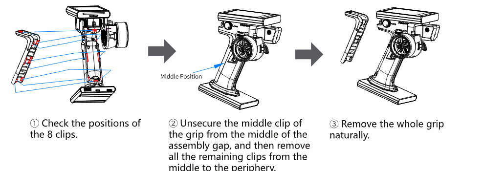
- Check the positions of the 8 clips.
- Unsecure the middle clip of the grip from the middle of the assembly gap, and then remove all the remaining clips from the middle to the periphery.
- Remove the whole grip naturally.
Steps for assembling the grip:
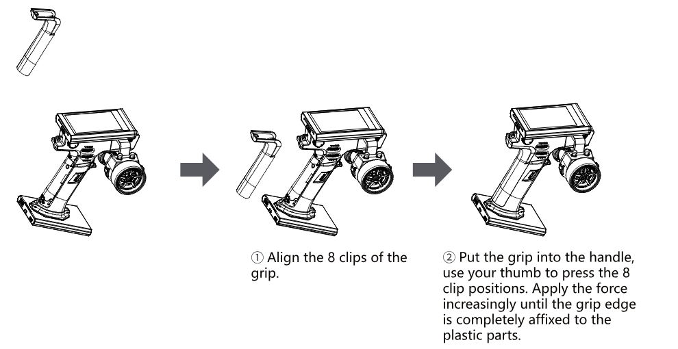
- Align the 8 clips of the grip.
- Put the grip into the handle, use your thumb to press the 8 clip positions. Apply the force increasingly until the grip edge is completely affixed to the plastic parts.
4Operation Instructions
After setting up, follow the instructions below to operate the system.
4.1Powering On
Note: This function has been updated in version 1.0.9 and later.
Follow the steps below to turn on the transmitter:
- Make sure that the battery is fully charged and installed correctly, and that the receiver is installed correctly and powered on.
- Hold the power button until the screen turns on. After power-on, the system will pop up a window to prompt whether to set up failsafe for the current model. To disable the failsafe setting prompt, tap [NO] or turn off the [Failsafe Warning] via [SYSTEM].
- Operate with caution in order to avoid damage or injury.
- Make sure that the throttle is at its lowest position and the switches are set to their up position.
4.2Binding
Note: This function was updated in version 1.0.22.
Ex-factory bind setting between transmitter and receiver is completed successfully. If you need to re-bind them, please follow the following steps.
Notes:
- Receivers equipped with AFHDS 3 protocol come in classic edition and enhanced edition. Models of classic edition: FGr4, FGr4S, FGr4P, FTr4, FTr10 and FTr16S (there will be pop-up menus). Models of enhanced edition: FGr4B, FGr8B, FGr12B, FTr8B, FTr12B, GMr, TMr and etc.
- When there is a stable two-way communication established between the transmitter and the receiver, the transmitter recognizes the receiver as a non FLYSKY receiver, the system will prompt and interrupt the communication.
- Refer to [6.10 MODEL] -> [Radio Frequency Setup] -> [RF Std.] to view or set the option to either [AFHDS3 2Way] or [AFHDS3 1Way].
Classic Version (Take FGr4P as an example)
Classic version receiver mode is only applicable to adaptations between the transmitter and receivers such as FGr4P, and etc.
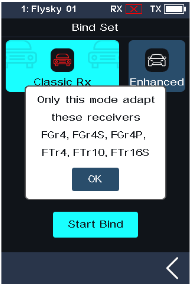
- Turn on the transmitter. Click the menu icon and enter the [RX SET], and select [Bind Set] in the menu.
- Click [Classic RX]. Then click [Start Bind].
- Insert the bind cable into the receiver's BIND port, and plug the power cable into any other port. At this time, the receiver LED will flash quickly, indicating it is in binding mode. When the RF standard selection is AFHDS3 2 way, the receiver LED is solid on, indicating the binding is successful. The transmitter will automatically exit the binding interface. When the RF standard selection is AFHDS3 1 way, after the receiver LED becomes slow flashing, then put the transmitter to exit the binding state. At this time, the receiver LED is solid on indicating the binding is successful.
- Take off the binding cable and the power cord from the receiver.
- Reconnect the power cord to the receiver. Check whether the servo is working properly. If a binding is required again, repeat the above steps.
Enhanced Version
Bind Mode
This transmitter supports two enhanced receiver binding modes: One RX Mode and Two RX Mode.
[One RX Mode]: Suitable for regular model operation, meeting basic control requirements.
[Two RX Mode]:
- When One RX Mode cannot meet the functional requirements of complex models, this mode can be activated. A single FGr4B receiver with only 4 channels might not meet the model's functional requirements. In this case, you can use a Two RX Receiver mode. By using two FGr4B receivers and setting the slave receiver's start channel to Channel 5, the system can output 8 channels.
- In this mode, when the same starting channel is set, the output signals are identical. If one receiver in the Two RX Mode is disconnected, the connection of the other receiver remains unaffected.
Modulation Type
Here are the introductions of [Routine] and [Antijamming Priority].
| Modulation | Key Features | Application Scenarios |
|---|---|---|
| Routine | In [Routine] mode, the system provides a balanced performance, offering moderate anti-interference capabilities and a moderate maximum control distance. | The [Routine] mode is suitable for most non-demanding scenarios, such as casual weekend use in parks. These environments typically feature open spaces with occasional WiFi signals or 2.4GHz devices (but not heavy interference). In such cases, neither extreme control range nor high-intensity interference resistance is required. |
| Antijamming Priority | In [Antijamming Priority] mode, the system uses high-density data packets. This keeps communication reliable even with lots of interference and packet loss. But it doesn't help with distance in low-interference situations. | This mode prioritizes stable connectivity in complex electromagnetic environments. By compromising maximum operational range, it ensures reliable performance in high-interference scenarios such as in large-scale competitions or environments with complex signal interference. |
One RX Mode
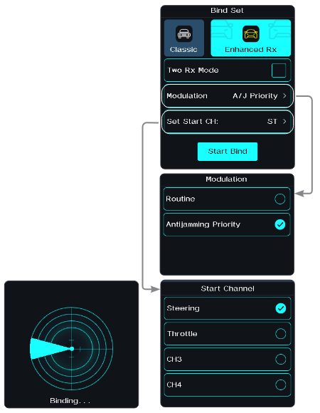
- Turn on the transmitter. Click the menu icon and enter the [RX SET], and select [Bind Set] in the menu.
- Click [Enhanced RX]. The system displays a pop-up prompt. Then click [Yes].
- For the [Two RX Mode] function box on the right, leaving it unselected configures the system for One Receiver Mode.
- Set the appropriate modulation mode and starting channel. To set the modulation mode: Select the [Modulation Mode] option to enter its settings menu. Tap your desired modulation mode. Then click the back arrow to return to the previous interface. To set the starting channel: Select [Set Start CH] to enter the next level interface. Tap the desired channel according to your needs. If set to Channel 3, Receiver CH1 outputs Transmitter CH3's signal. Then click the back arrow to return to the previous interface.
- Tap [Start Bind] to put the transmitter into binding mode.
- Press and hold the BIND button on the receiver while powering it on. When the receiver LED flashes rapidly, it indicates that the receiver has entered binding mode. When the RF standard selection is AFHDS3 2 way, the receiver LED is solid on, indicating the binding is successful. The transmitter will automatically exit the binding interface. When the RF standard selection is AFHDS3 1 way, the receiver LED flashes slowly; after the receiver LED becomes slow flashing, then put the transmitter to exit the binding state. At this time, the receiver LED is solid on indicating the binding is successful.
- Check to make sure the transmitter and receiver are operating normally, repeat steps if any problems arise.
Two RX Mode
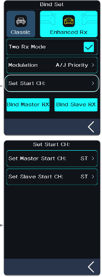
- Turn on the transmitter. Click the menu icon and enter the [RX SET], and select [Bind Set] in the menu.
- Click [Enhanced RX]. The system displays a pop-up prompt. Then click [Yes].
- Click the function box to the right of [Two RX Mode]. Check it to enable two receiver mode. Then, proceed to set the appropriate modulation mode by referring to Step 4 under 'One RX Mode'.
- Click [Set Start CH:] to enter the setting interface.
- Set the starting channel for the master receiver. Select [Set Master Start CH:] to enter the next-level interface. Then, proceed to set the appropriate starting channel by referring to Step 4 under 'One RX Mode'. Tap the back arrow to return to the previous interface.
- Set the starting channel for the slave receiver.
- Click [Bind Master] to put the transmitter into binding mode, then activate the binding mode on the primary receiver to complete the binding process.
- Click [Bind Slave] to put the transmitter into binding mode, then activate the binding mode on the secondary receiver to complete the binding process.
- Check to make sure the transmitter and receiver are operating normally, repeat steps if any problems arise.
Notes:
- The default mode is One RX Mode.
- The operation to enter binding mode varies slightly depending on the receiver model. Please refer to the receiver's manual for specific instructions.
- The products are subject to constant update. Please enter FLYSKY website for the latest transmitter and receiver compatibility form.
4.3Transmitter LED Indicator
The transmitter LED color can be customized, or you can select one of the five colors defined in the options (Red, Green, Blue, Yellow or White), and the LED brightness can be adjusted. The LED display can also be turned off or set to indicate the transmitter battery power by using the [Battery Indicator] function.
To change the LED color see the 8.8 LED section of this user manual.
4.4Powering Off
- Make sure to disconnect the receiver power before turning off the transmitter. Failure to do so may lead to damage or serious injury.
Follow the steps below to turn off the system:
- Disconnect the receiver power first.
- Hold the transmitter power button until the screen turns off.
5System Interface
Note: This function has been updated in version 1.0.9 and later.
The main interface mainly displays information related to the model, such as transmitter voltage information, function status and so on.
The display on the main interface can be customized as required, including the states and data of the main interface. Up to 8 states and data can be displayed.
Main interface left slide: Channel display; right slide: Failsafe; upward slide: Timer; downward slide: System settings. If you need to change settings, see 8.11 Quick Access.
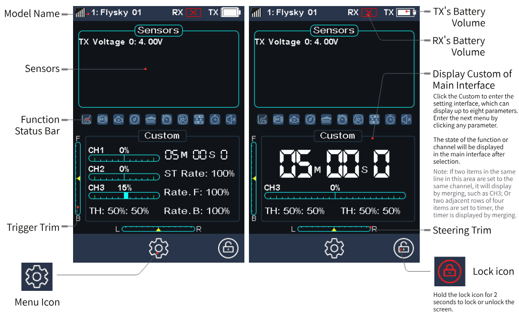
| Model Name | The name of the current model. |
| Sensors | Sensor data returned by the receiver. |
| Function Status Bar | The status of various functions. |
| Trigger Trim / Steering Trim | The current trim positions. |
| TX's / RX's Battery Volume | The battery level of the transmitter and the receiver. |
| Display Custom of Main Interface | Click Custom to enter the setting interface, which can display up to eight parameters. Enter the next menu by clicking any parameter. The state of the function or channel will be displayed in the main interface after selection. Note: If two items in the same line in this area are set to the same channel, it will display by merging, such as CH3; or if two adjacent rows of four items are set to timer, the timer is displayed by merging. |
| Menu Icon | Opens the menu. |
| Lock icon | Hold the lock icon for 2 seconds to lock or unlock the screen. |
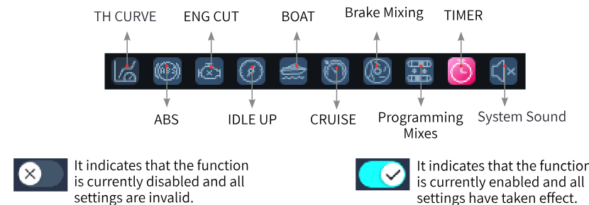
Function Status Bar
The function status bar displays the status of various functions. If the function shows in bright color, then it is active; if it is light gray, then it is inactive.
6Function Settings
This section introduces details of the functions and their use.
Notes:
- The default ex-factory state of this transmitter allows the user to set the functions under CH1-CH4; follow the steps for specific function settings for other channels (refer to Channel Number Definition of 6.10 MODEL for setting 6 channels or 8 channels).
- Some functions are disabled by default, and you may need to tap the on/off icon and enable the function for the setting to take effect.
- The function menus may vary with the receiver protocols. The actual product menu shall prevail.
6.1REV
The REV (Reverse function) is used to correct a servo or motor's direction in relation to the system's controls.
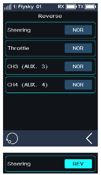
Setup:
- Touch the box next to the channel's name. If the channel is in normal mode, the box will display "NOR"; if it is reversed it will display "REV".
- Test to make sure everything is working as expected.
6.2EPA
Endpoints are the limits of the channel's range of movement. There are two endpoints, a low endpoint and a high endpoint.
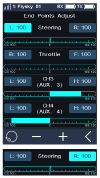
Setup:
- Touch a low or high endpoint box on a channel or move the control to the direction you wish to limit. The selected endpoint will be highlighted in green.
- Use "+" and "-" to change the end point position (press and hold to accelerate the adjustment). The maximum is 120% and minimum is 0%.
- Test to make sure everything is working as expected.
6.3SUB TR
SUBTRIM can be used to adjust the error of the structure by changing the channel neutral position.
For example, if a car's wheels are slightly out of alignment, even when the transmitter steering wheel is not being touched, subtrim can be used to correct the alignment.
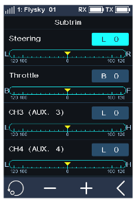
Setup:
- Touch the box next to the channel name to select it. When selected, the box will be highlighted.
- Use "+" and "-" to change subtrim position.
- Test to make sure everything is working as expected.
6.4ST DR/EXP
This function changes the steering channel's response curve.
This function is enabled by default; click the on/off icon to disable the function, then the icon changes to off.
This function can be switched on or off through SW controls, and the corresponding rates and curves can be tuned by other trims or knobs. Please refer to [Assign] function for setting.
There are 2 main parameters:
- [Rate]: Changes the outer limits of the steering; the default and maximum is 100%.
- [Exp]: Changes the steering curve, which changes the response of the steering wheel. The Exp. setting can be positive or negative.
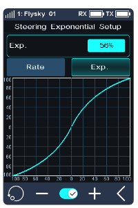
Setup:
- Touch [Rate] or [EXP] (when an option is selected, it will be highlighted).
- Use "+" and "-" to raise or lower the percentage as needed. The rate value increases in case of clicking "+", and decreases by clicking "-".
- To turn off the function, touch the on/off icon. The icon changes to off, then the function is disabled.
- Test to make sure everything is working as expected.
6.5TH DR/EXP
This function, which is similar to the ST DR/EXP function, is used to control the throttle channel.
This function can be switched on or off through SW controls, and the corresponding rates and curves can be tuned by other trims or knobs. Please refer to [Assign] function for setting.
- [Rate.F] and [Rate.B]: Used to adjust the slope of the forward or brake curve; the smaller the rate is set, the smaller the slope. The maximum range is 100%.
- [Exp.F] and [Exp.B]: Changes the forward or brake curve. When the value is set to 0, the curve changes to a line. The setting range is -100% – 0 – 100%.
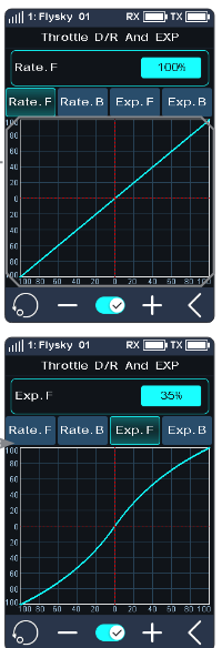
Setup:
- Touch [Rate.F], [Rate.B], [Exp.F] or [Exp.B].
- Use "+" and "-" to raise or lower the percentage as needed. The curve slope increases when touching "+" and decreases by touching "-".
- Repeat for the other setting as needed.
- Test to make sure everything is working as expected.
6.6ABS
A.B.S. stands for auto braking system. This function is used to stop the wheels from locking which can lead to loss of control or a skid. A.B.S. manages this by regulating the amount of pressure the brakes use, which is done by pumping the brakes on and off rather than a constant force.
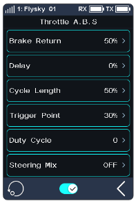
There are six sub menus for A.B.S. function setting: [Brake Return], [Delay], [Cycle Length], [Trigger Point], [Duty Cycle], and [Steering Mix].
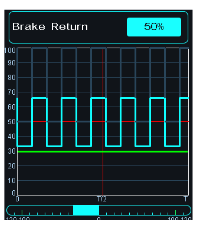
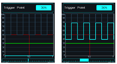
In the submenus, pulses are shown as a square wave, the peaks indicating brake on, and troughs indicating reduction in braking. As the value changes, the square wave will change to represent the function's current settings.
The trigger point is represented as a white line on the graph.
Below the graph is a bar that shows the real-time braking position. When this function is active and the brake is applied, the green bar will oscillate in real time showing the A.B.S. in action.
To activate this function press the on/off icon. The icon will change to on when active.
Brake Return
Controls the reduction of braking during each pulse. Can be set to any value between 0% and 100%. By default it is set to 50%. If set to 60%, when the brakes are active, the system will remove 60% of the brakes' strength on each pulse.
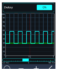
Delay
Determines how long it takes for the A.B.S. system to take effect. At a setting of 0%, the A.B.S. system will take effect as soon as the brake is applied. The higher the value, the longer it will take for the A.B.S. to function.
When set to 0% there will be no delay, meaning the brakes will be applied as soon as they are triggered. The maximum setting of 100% will result in a delay of 2 seconds.
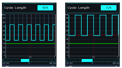
Cycle Length
Increases or decreases the time between pulses. The higher the value, the longer the pulse. The maximum setting of 100% will result in a cycle length of 0.5 seconds.
Trigger Point
Configures the point at which the A.B.S. starts to function. The higher the percentage, the further the trigger has to be moved to activate the A.B.S. 0%-100% represents the entire stroke of the braking servo.
Duty Cycle
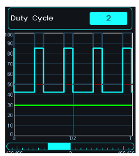
Changes the length of each pulse and the gap between them. Adjustment range is from -4 to +4 cycles. As the value changes, the length of the braking wave's peaks and troughs will change independently of each other and will no longer be symmetrical.
Adjusting the brake to release ratio: When the period is set to "0", the ratio is 1:1; when the period is set to "1", the ratio is 1:2; when the period is set to "-1", the ratio is 2:1.
Steering Mix
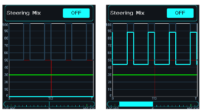
A.B.S. can be enabled or disabled automatically while turning when mixed with the steering wheel.
The percentage represents the trigger position through its entire range of movement. E represents inside, N represents outside; if 50% N is set, the ABS function is turned off within 50% (10% N–50% N), and outside 50% (50% N–100% N) the ABS function is turned on. If 50% E is set, the ABS function will be turned on within 50% (10% E–50% E), and the ABS function will be turned off outside 50% (50% E–100% E).
Setup:
- Touch the on/off icon to enable this function.
- Touch a setting to select it.
- Touch "+" or "-" to change the value.
- Repeat as needed.
- Test to make sure everything is working as expected.
6.7TIMER
Note: This function was updated in version 1.0.17.
This function can set a variety of timers, to generally calculate the total model run time, competition specific time spent, or transmitter run time, etc.
The function can be enabled, disabled or cycle-counted by SW controls, and the timer can be reset at one touch. Please refer to [Assign] function.
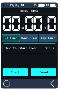
The timer function can be activated in three modes:
Mode I:
- Click the [Timer Mode: Up Timer]. Then click the corresponding function as needed. Click the back arrow to return to the previous interface.
- Click [Start] to start the timer. Click [Stop] to stop the timer. Click [Reset] to reset the single timer function to its default value.
Mode II:
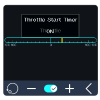
- Click the [Throttle Start Timer]. Click "+" or "-" to change the throttle start value. Press "+" or "-" for seconds to accelerate the throttle start value. The value change level is 1, and the level range is -100 to 100. Users can adjust it as desired.
- Click the on/off icon to enter the Controls Assign menu. Assign a control to enable or disable the function. When this function is enabled, the icon will change to on. Enabling/disabling the timer through the control triggers a floating notification.
- Verify that the setting is normal as expected. Namely, when the throttle is adjusted to the set value, the timer will start timing.
Mode III:
The timer can be enabled or disabled quickly through a control assigned via the ASSIGN function. Enabling/disabling the timer through the control triggers a floating notification.
The system will send out a reminder when it reaches a minute sharp.
The race timer has 3 modes:
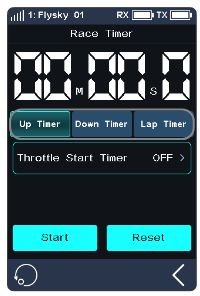
- [Up Timer]: Start the clock from zero.
- [Down Then Up Timer]: Countdown from the set time; the shortest time is 1 second. The system will send out a reminder when it reaches a minute sharp. When the countdown is less than 1 minute, the system will give a voice prompt at 30 seconds, 20 seconds, 15 seconds. And when the countdown time has only 10 seconds left, the system will send a voice prompt every second. When the timer reaches 0, the system will send a voice prompt that the timer time is up, and start the up timer. Click [Down Then Up Timer]. Then click the minutes or seconds display interface, and click "+" or "-" to change the duration. Press and hold the "+" or "-" to accelerate the adjustment. The maximum duration is 99 minutes and 59 seconds.
- [Lap Timer]: Keeps track of the time for each individual lap. Once triggered the on icon will become the lap icon. Each time the lap icon is pressed the last lap will be recorded in the lap timer list. The maximum number of laps is 99 and the minimum lap time must be over 3 seconds.
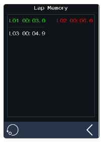
- [Lap Memory]: Records the results from the lap timer.
6.8ASSIGN
Note: This function was updated in version 1.0.17.
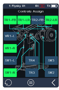
The key assignment function is used to assign keys or switches to different functions/channels for quick switch or control. If the base color of a control is green, it indicates the control has been assigned.
SW Controls
The keys SW1L, SW1R, SW2 and SW3 can enable, disable or switch CH3 to CH8 and many functions. The combo of SW2 and SW3 can adjust the values of the selected channels and functions.
Note: The number of channels to control depends on [Channel Number Definition].
- [Function]: Assign functions to this key or knob.
- [Direction]: Used to set the forward or reverse of this button or knob.
- [Mode]: When "Trigger" is selected, channel data will change once through key triggering. Channel data will return to the state before key operation when the key is released. When "TURN" is selected, channel data remains in effect at the time of trigger if the button is rebounded.
- [Step]: Step, which is used to adjust the value change of a single operation. "1" means move the key once, the value change level is 1; the level range is 1-120, the user can adjust it as needed.
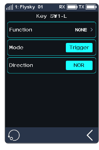
Setup:
- Touch [SW1-L] or any of the other button icons.
- Touch [Function], then touch function or channel as desired. If the function or channel has been assigned to another key, the system will prompt "The function is already assigned to SW2. Are you sure? Assigned to SW1-L." Click [Yes] to switch.
- Click the [Trigger] option on the right side of [Mode]. Then [TURN] is displayed. It indicates that channel data is changed once for each trigger of this button, and the data is kept in the state of the trigger as effective.
- Click the [NOR] option on the right side of [Direction]. Then [REV] is displayed. It indicates the actual operation of this button is reversed with the output.
Switching to C BTN (combination button)
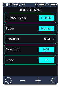
- Click [SW2] or [SW3] to enter the submenu, then click [Button Type S BTN] to switch to [C BTN]. [Button Type S BTN] means the key or knob can control enabling, disabling, or switching from one direction separately. [Button Type C BTN] means the key or knob can adjust the function or channel values in two directions (upward and downward).
- Click [Type], switch between [Normal], [2 POS], and [3 POS] as required.
- Touch [Function] when the type is set to Normal, touch the function as desired, and click the back arrow to return to the previous interface. A key or switch can be assigned one function or channel. When [Type] is set to [2 POS] or [3 POS], the function cannot be assigned.
- Click the [NOR] option to the right of [Direction]; the display of [Reverse] indicates that the actual operation of this button is reversed with the output.
- Click [Step], then use "+" or "-" to change the value. When [Type] selects [2 POS] or [3 POS], the step value is not adjustable.
TR Controls
The six keys or knobs (TR1-FB, TR1-LR, TR2-FB, TR2-LR, TR3, and TR4) have the same function and can be used to quickly adjust the values of CH3 to CH8 and multiple functions, with assigning 2-position or 3-position switches.
Note: The number of channels controlled is subject to the [Channel Number Definition].
The operation procedure of this function is basically the same as the SW control setting.
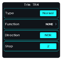
VR Controls
The functions of VR1-L and VR1-R are the same as above. However, the step is not adjustable.
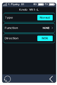
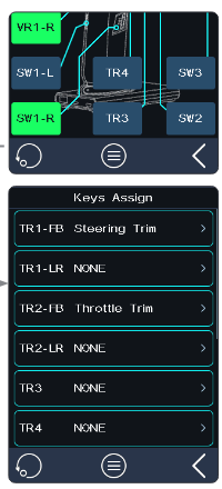
Keys Assign
Click the list icon to enter the [Keys Assign]. In this list, you can view detailed information about the function assignment of all keys and knobs.
You can directly click the corresponding button function to set the function.
6.9NAME
You can customize the function name based on the channel function name. You can also choose a preset channel name.
Preset Channel Names
Steering, Throttle, Trim Tab1, Trim Tab2, Aux.ST, F Diff, C Diff, R Diff, Shift, Gearbox, T Case, CutGear, Lights, H Beam, L Beam, F Light, T Light, Smoke, Whistle, Capstan, Ecas, Engine.
Note: The number of channels is subject to the [Channel Number Definition].

Setup:
- Click [NAME] to enter the interface.
- Click the corresponding channel. Press [Enter] for confirmation. Click the back arrow to return to the previous level interface. A name can be set to any combination of letters, numbers or symbols.
- If you want to select a preset name, click the preset icon. Click the corresponding name as needed, then click the save icon. When the name is saved, the icon changes. Click the back arrow to return to the previous level interface.
6.10MODEL
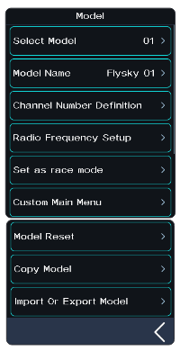
The model functions are used to change, reset, rename, copy or customize the display and sorting of the main menu. The Noble NB4+ can store up to 25 models.
Select Model
Selects a model. Touch [Select Model], then touch a model from the list. Then click "Yes" in the prompt menu.
Name: FlySky 01
To name the model. After clicking, use the keyboard in the interface to type in a new name. When the setting is finished, click "Enter" to save the setting. Click the back arrow to return.
Channel Number Definition
This function is used to select the number of channels (2~8 channels).
When selecting a receiver, ensure its channel capacity matches your transmitter's configuration. Choosing a receiver with insufficient channels may limit your transmitter's functionality, while opting for excessive channels will result in unused channel resources.
Configuration example: For systems requiring ≤ 4 channels (e.g., FGr4B with 4 PWM outputs), set your transmitter to 4-channel mode. When expanding to 8 channels using PWM converters or selecting dual RX mode, configure your transmitter for 8-channel operation.
Note: When the user selects 2 channel (Fast), it is the maximum speed mode.
Tap [Channel Number Definition], then tap the channel number as desired, click "Yes" in the prompt menu.
If the larger number of channels is switched to the lower number of channels, the system will prompt "The model will reset, need re-binding. Are you sure?". Click "Yes". Switching is successful. If the lower number of channels is switched to the larger number of channels, the system will prompt "After switching you need re-binding. Are you sure?". Click "Yes". Switching is successful.
Radio Frequency Setup
It includes RF protocol setup and RF module update of the transmitter and receiver.
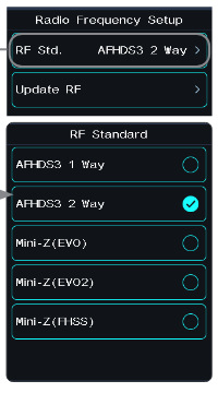
RF Std. (RF Standard)
- [AFHDS3 1 Way]: It features lower latency, allowing one transmitter to connect multiple receivers. It is applied when the model does not need any return data.
- [AFHDS3 2 Way]: With the two-way return function, it can return feedback data from receivers and sensors and realize one transmitter to one receiver.
- [Mini-Z(EVO)]: Used with FS-minizRF3 receiver to control Kyosho Mini-Z EVO car. The number of channels is fixed (two channels).
- [Mini-Z(EVO2)]: Used with FS-minizRF3 receiver to control Kyosho Mini-Z EVO2 car. The number of channels is fixed (two channels: steering and throttle).
- [Mini-Z(FHSS)]: It is used with a Kyosho FHSS receiver to control the cars of Kyosho Mini-Z FHSS. The number of channels is fixed (four channels).
FS-RM005 RF head supports a Noble+ transmitter. It is only compatible with Kyosho Mini-Z (FHSS) cars.
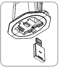
Binding steps when using FS-RM005 RF module:
- Remove the transmitter base's mobile power supply and insert the RF head into the transmitter base correctly (as shown in the figure).
- Click [MODEL]. Select the RF Setup and set RF Standard as Mini-Z (FHSS).
- Insert FS-RM005 RF module and re-install the transmitter base power supply.
- Connect the power cord to the transmitter. Press the receiver bind key while connecting the receiver power supply. At this time, the receiver LED indicator flashes quickly. Operation modes vary with receivers in case of their bind state. When Mini-Z(FHSS) is not selected, the FS-RM005 RF module does not have the RF transmit function, and its power supply is turned off.
- Click [RX SET]. Select [Bind Set]. After the receiver LED flashes slowly, the transmitter will automatically exit the binding state. When the receiver LED is solid on, it indicates the binding is successful.
- Check whether the servo is working properly. If a binding is required again, repeat the above steps.
Change the RF Protocol
Click [RF Std. (RF standard)] to enter the submenu. Click the right side of the corresponding function. Select "Yes" after the prompt box pops up and click the back arrow to return to the previous level interface.
- If you switch the RF standard, the model will be reset and a bind is required again.
Update RF
The update RF function can be used to update the firmware of the built-in RF module. After the firmware of the transmitter is updated, you need to update the RF when the system prompts that the RF fails or the bind of the receiver fails.
Click [Update RF], click "Yes" after the prompt interface pops up. An update progress bar appears. Wait a few seconds. The update is completed. The transmitter will automatically exit the update interface. If the transmitter cannot enter the update RF status, there is no RF module or the RF module is faulty.
Set as Race Mode
Note: This feature is only applicable to version 1.0.12 and later.
This function is used to quickly disable the Low signal alarm and Telemetry loss alarm, effectively turning off the signal-related alarms. It is recommended to use this function to disable the Low signal alarm and Telemetry loss alarm before a race; after the race, you can decide whether to re-enable these two alarm functions based on the actual usage scenario (to enable: menu > RX SET).
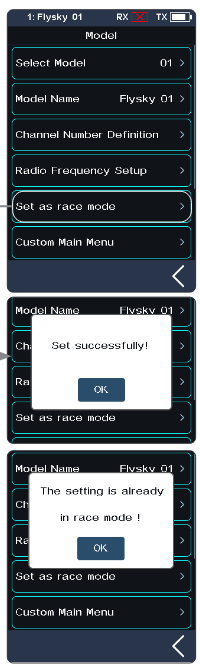
Setup:
- Enter [Model] interface.
- Tap [Set as race mode], and the system will pop up a message indicating the setting is successful, meaning the relevant alarms have been disabled; tap [OK] to close the pop-up window. If you tap [Set as race mode] again, a pop-up message will indicate that the system is already in race mode; tap [OK] to close the pop-up window.
Custom Main Menu
You can customize the sort and hide functions of the main menu. To show the menu, select the check box. To hide the menu, uncheck the box. To adjust the menu order, select the menu to move (highlighted), and click [Move up] or [Move down] below to change the menu order.
Note: By default, the "Beginner Mode" function is hidden. Except for [System] and [Model], all other functions can be hidden.
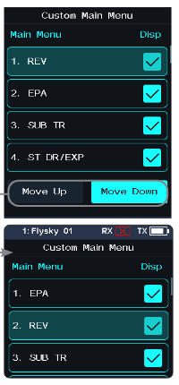
Model Reset
To reset a model. Touch [Model reset], then select the model you wish to reset from the list. The system will ask if you are sure; select "Yes".
Copy Model
To duplicate a model. Touch [Copy Model], then touch the model to copy from the list. Next select a target slot from the list; this will overwrite everything in that slot. The system will ask if you are sure; select "Yes".
Import or Export Model
You can import and export models by FlySky Assistant which can be downloaded via the FlySky official website, and then operate it on the PC (no need to go back to click the menu on the transmitter, you can operate it directly)!
6.11SENSOR
Note: This function was updated in version 1.0.22.
This function can display the sensor information received by the receiver on the transmitter.
This function shows all sensors connected to the receiver, including sensor type, ID and real-time value.
It can also be accessed quickly from the home screen.
This function is available when the receiver is bound to the transmitter using the AFHDS 3 2 Way protocol.
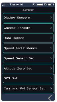
Display Sensors
This list displays all sensor data connected to this transmitter device, including sensor type, ID, real-time value, and polarity and limit values.
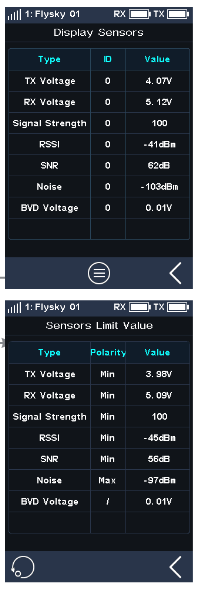
- [Type]: To show the sensor type.
- [ID]: To display the sensor's number. By default, the number zero in the list includes the TX Voltage, RX Voltage, Signal strength, RSSI, Noise and SNR. No. 1 is the return information of the Slave (secondary) receiver. No. 2 is the first external sensor connected to the receiver, and so on, up to 14 sensors in total. This list data is displayed in real time. When the receiver is connected to a sensor, this list will be refreshed to display the new sensor's data. When the sensor is disconnected, the sensor data will not be displayed.
- [Value]: To display the data returned by a sensor.
Sensor Limit Value: To display the extreme value information of the connected sensor. Click the list icon to enter the submenu which displays the limit value.
- [Type]: To show the sensor type.
- [Polarity]: To display the polarity to be recorded by the corresponding sensor: maximum, minimum, or "/".
- [Value]: To record and display the actual limit value of the corresponding sensor.
To clear all records, click the reset icon.
Note: "/" indicates that the extreme value is not recorded. You can also clear extreme value records by assigning SW type controls through [ASSIGN].
i-BUS series sensor connection diagram

Notes:
- If using the AFHDS 3 classic edition receivers, you must select the [RX Interface Protocol] in the [RX SET] menu and select [i-BUS], save and exit, then connect the sensor to the receiver's i-BUS port. All other steps remain the same.
- If you use an enhanced edition receiver, you need to set the New Port interface to i-BUS in.
Speed sensor (FS-CPD01, FS-CPD02)
The speed sensor is applied to test the speed of the motor. "Motor speed" indicates that the sensor is testing the motor speed; "0rpm" is the speed measurement value.
Magnetic induction speed sensor (FS-CPD01)
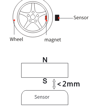
- Connect the FS-CPD01 sensor to the receiver or other sensors connected to the receiver using the same method as shown above.
- Place the sensor next to the magnet, which is fixed at the position of the axial rotation to be tested (e.g. inside the wheel hub of the model car).
- Place the sensor within 2 mm of the magnet, with the south or north pole of the magnet parallel to the sensor.
- Turn on the transmitter, and select [Sensor] > [Display Sensors]. Turn the gear. When the [Type] column shows "RPM" and the RPM value (0rpm) in the [Value] column changes, it indicates that installation is successful. Otherwise, repeat the above steps.
Light induction speed sensor (FS-CPD02)
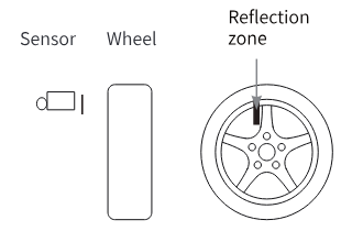
- Connect the FS-CPD02 to the relevant device, with the same connection method as above.
- Fix the sensor and the reflective sticker at the position of the axial rotation to be tested. Keep the sticker flat and perpendicular to the sensor probe. Keep a moderate distance between the sensor probe and the sticker.
- Turn on the transmitter, and select [Sensor] > [Display Sensors]. Turn the gear. When the "Type" column shows "RPM" and the RPM value (0rpm) in the "Value" column changes, it indicates that installation is successful. Otherwise, repeat the above steps.
Temperature Sensor (FS-CTM01)
Used to monitor the temperature of various components. The temperature of the component can be monitored via the transmitter. Alarms can be set.
- Connect the FS-CTM01 to the receiver or other sensors using the same method as used with other sensors.
- Use a spongy double-sided tape to stick the temperature probe to the part you wish to monitor (such as motor, battery).
- Turn on the transmitter, enter [Sensor] > [Display Sensors] and rotate the wheel. If the "Type" column displays "Temperature" and the "Value" column displays a temperature then the installation was successful, otherwise repeat the above steps.
Voltage sensor (FS-CVT01)
It is used to monitor the model's battery voltage. The battery voltage can be monitored through the transmitter. Alarms can be set.
- Connect FS-CVT01 following the same steps as above.
- Insert the red and black wire pins into the plug of the battery used for testing. The red wire is the power anode and the black wire is the power cathode. Make sure to connect correctly.
- Turn on the transmitter, enter [Sensor] > [Display Sensors] menu and rotate the wheel. If the "Type" column displays "External Voltage" and the "Value" column displays a voltage then the installation was successful, otherwise repeat the above steps.
i-BUS2 Series Sensor Connection Diagram
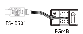
Notes:
- The i-BUS2 series sensors are only compatible with AFHDS 3 enhanced edition receivers. Take the FS-iBS01 sensor connection diagram as an example. The method for connecting other i-BUS2 sensors is the same.
- The i-BUS2 series sensor must be connected to the New Port of the receiver, and set the New Port interface protocol to i-BUS2 via [RX SET] > [Receiver Interface Protocol].
i-BUS2 Optical Perception Sensor (FS-iBS01)
It is used to monitor the model's speed, such as motor speed. Alarms can be set. "Motor Speed" indicates that the sensor is testing the motor speed; "0rpm" is the speed measurement value.
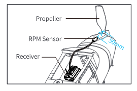
- Use 3M stickers to fix the sensor at the appropriate location of the model as shown in the figure. And make the optical perception detection element perpendicular to the reflective surface of the motor rotor. It should be noted that the fixed surface should be flat. You can also use a cable tie to tie it to the model. In this case, you should control the force.
- Connect the sensor to the receiver using the same method as shown above.
- Turn on the transmitter, enter [SENSOR], then select [Display Sensors] menu. When the "Type" column shows RPM and the RPM value (0rpm) in the "Value" column, it indicates that installation is successful. Otherwise, repeat the above steps. The distance between the optical perception detection element and the propeller or rotor is not more than 50 mm or 30 mm (with a light shield).
Note: Please refer to the FS-iBS01 manual for more details.
i-BUS2 Altitude Sensor (FS-iBA01)
It is used to monitor the model's altitude. Alarms can be set. "Air Pressure" indicates that the sensor is monitoring air pressure; "Height" means the height measurement, "Altitude" is the altitude measurement.
- Use 3M stickers to fix the altitude sensor at the appropriate location of the model. It should be noted that the fixed surface should be flat. You can also use a cable tie to tie it to the model. In this case, you should control the force.
- Connect the sensor to the receiver using the same method as shown above.
- Turn on the transmitter, enter [SENSOR], then select [Display Sensors] menu. When the "Type" column shows Air Pressure, Height, Altitude and their values in the "Value" column, it indicates that installation is successful. Otherwise, repeat the above steps.
Note: Please refer to the FS-iBA01 manual for more details.
i-BUS2 Temperature Sensor (FS-iBT01)
It is used to monitor component temperature. Alarms can be set.
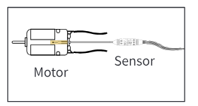
- Use 3M stickers to fix the temperature sensor at the appropriate location of the model. It should be noted that the fixed surface should be flat. You can also use a cable tie to tie it to the model. In this case, you should control the force.
- Use soft glue to stick the temperature detecting element on the parts to be detected, for example, motor, ESC or engine.
- Connect the sensor to the receiver using the same method as shown above.
- Turn on the transmitter, enter [SENSOR], then select [Display Sensors] menu. When the "Type" column shows temperature and the value in the "Value" column, it indicates that installation is successful. Otherwise, repeat the above steps.
Note: Please refer to the FS-iBT01 manual for more details.
i-BUS2 Current and Voltage Sensor (FS-iBC01)
It is used to monitor the information such as the voltage, current and actual battery consumption capacity of the ESC in real time.
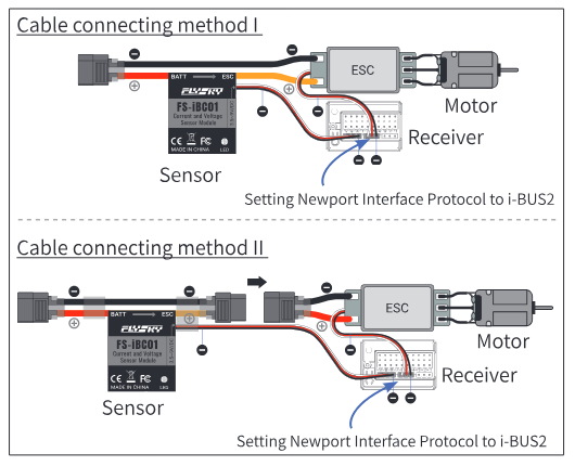
- Use 3M stickers to fix the sensor at an appropriate location of the model. It should be noted that the fixed surface should be flat. You can also use a cable tie to tie it to the model. In this case, you should control the force.
- Finish cable connecting according to the cable connecting diagrams as shown. Make sure the cables are connected correctly.
- Turn on the transmitter, enter [SENSOR], then select [Display Sensors] menu. When the "Type" column shows Curr and Vol, Voltage, Current, etc., and the corresponding values of voltage and current in the "Value" column, it indicates that installation is successful. Otherwise, repeat the above steps.
Note: Please refer to the FS-iBC01 manual for more details.
- Make sure to refer to the "Installation and Cable Connecting" section of the FS-iBC01 user manual for correct wiring. Otherwise, there may be an explosion or fire.
i-BUS2 Telemetry Adapter (FS-iBTA01)
It is used to convert the telemetry information of supported external devices into i-BUS2 protocol information and transmit it back to the transmitter.
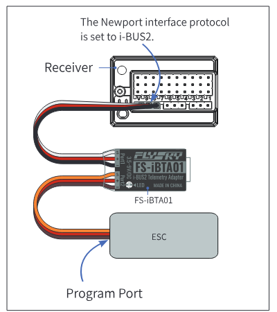
- Use 3M stickers to fix the sensor at an appropriate location of the model. It should be noted that the fixed surface should be flat. You can also use a cable tie to tie it to the model. In this case, you should control the force.
- Finish cable connecting according to the cable connecting diagrams as shown. Make sure the cables are connected correctly.
- Turn on the transmitter, enter [SENSOR], then select [Display Sensors] menu. When the "Type" column shows Temperature and Current, Revolution, etc., and the corresponding values of voltage and current in the "Value" column, it indicates that installation is successful. Otherwise, repeat the above steps. Before use, upgrade the ESC firmware to the latest version for optimal performance and feature support. Due to differences between ESC models, some models may only display relevant values after startup and operation.
Note: Please refer to the FS-iBTA01 manual for more details.
Choose Sensor
This function allows you to select the sensor to be displayed on the main screen and high and low alarm values for that sensor.
There are four settings under this function: [Transmitter Voltage], [Receiver Voltage], [Signal Strength] and [RSSI], for setting high and low alarm values of the corresponding sensor.
For example, the Signal Strength Indication (RSSI). It refers to the distance between the transmitter and the model determined by received signal strength. A low signal strength indicates a weaker signal received by the receiver. This may cause the model to lose signals. A high signal strength indicates that the signal received is too strong, and this may interfere with the signals of the receiver and cause the model to lose control. Therefore, users can also choose to set the strong alarm alert.
![Choose Sensors screen with 1. TX Voltage[0], 2. RX Voltage[0], 3. Signal Strength[0], 4. RSSI[0]](/manuals/nb4-plus/screen-choose-sensors.png)
Setup:
[TX voltage]:
- Enter this menu, then touch the on/off icon to enable this function. When this function is enabled, the icon will change to on.
- Touch [Low Alarm] to select. [Value] is the corresponding status alarm value. Touch "+" or "-" to change the trigger value. Same with the [High Alarm]. For example, set the low alarm value of the speed sensor to 200rpm; if the speed is lower than this value, then the transmitter will alarm, alarm mode: sound and vibration, and the corresponding item in the sensor display area of the main interface will blink red.
[RX voltage], [Signal strength], [RSSI] can all be set using the above instructions.
Data Record
Note: Before using this function, note that [RF Standard] needs to be set to [AFHDS3 2 Way].
This function is used to display and set data-record information.
![Data Record screen explained: the settings icon to set the sensor to be recorded; the page number of the coordinate diagram (1/10); the graph showing the selected sensor's data over time; the sensor buttons (Steering, Voltage-FXS (V), Current-FXS (A), Temp-FXS (°C)) to select the sensor to view; the reset icon to clear all recorded data (controls can also be assigned via [ASSIGN]); the on/off icon. The start/stop/reset of Data Record can be controlled by an assigned control via [ASSIGN]: click the control to pause the data record, and hold the control for 2 s to reset the record. When the function is paused, swipe the screen left or right to turn the page and view the related records.](/manuals/nb4-plus/data-record.png)
You can set the sensor to be recorded through Data Record Set.
- [Record Duration]: Selects the maximum duration of a data record.
- [Curve1~4]: Selects the function displayed by the curve (refer to the following table for the functions which can be set). Four curves can be set.
- [Max Value]: Sets the maximum value corresponding to the function. If the function of the curve is set to a non-channel, this function item appears.
- [Min Value]: Sets the minimum value corresponding to the function. If the function of the curve is set to a non-channel, this function item appears.
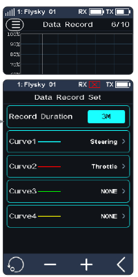
Setup:
- Click [Data Record], then touch the on/off icon to enable this function. When this function is enabled, the icon will change to on.
- Click the settings icon to enter the data record set menu.
- Click the curve to enter, then select an appropriate function as desired. Click the back arrow to return.
- Click [Max Value], then touch "+" or "-" to change the value. The setting of [Min Value] is the same.
Supported Devices, Default Values and Setting Ranges of Data Record
| Device | Type | Min Value | Max Value | Setting Range | Step | Unit |
|---|---|---|---|---|---|---|
| Transmitter | Voltage | 3 | 5 | 0~10 | 1 | V |
| Receiver | Voltage | 4 | 6 | 0~10 | 1 | V |
| Receiver | BVD Voltage | 5 | 10 | 0~100 | 1 | V |
| Receiver | Signal | 0 | 100 | 0~100 | 1 | / |
| Voltage Sensor | External Voltage | 5 | 10 | 0~100 | 1 | V |
| Temperature Sensor | Temperature | 0 | 80 | -100~200 | 10 | ℃ |
| Altitude Sensor | Altitude | 0 | 100 | -1000~1000 | 10 | m |
| RPM Sensor | Rotational Speed | 0 | 5000 | 0~99900 | 100 | rpm |
| RPM Sensor | Speed | 0 | 60 | 0~300 | 10 | km/h |
| GPS | Speed | 0 | 60 | 0~300 | 10 | km/h |
| GPS | Altitude | 0 | 100 | -1000~1000 | 10 | m |
| GPS | Acceleration | 0 | 10 | -20~20 | 1 | m/s² |
| FXS Servo | Angle | -80 | 80 | -100~100 | 10 | ° |
| FXS Servo | Angular Velocity | -200 | 200 | -1000~1000 | 10 | °/s |
| FXS Servo | Voltage | 4 | 6 | 0~10 | 1 | V |
| FXS Servo | Current | 0 | 10 | 0~100 | 1 | A |
| FXS Servo | Temperature | 0 | 80 | -100~200 | 10 | ℃ |
| PowerHD Servo | Voltage | 4 | 6 | 0~20 | 1 | V |
| PowerHD Servo | Temperature | 0 | 80 | -100~200 | 10 | ℃ |
| PowerHD Servo | PWM Duty Cycle | 0 | 100 | 0~100 | 10 | / |
| HW ESC | Voltage | 5 | 10 | 0~100 | 1 | V |
| HW ESC | Current | 0 | 10 | 0~1000 | 1 | A |
| HW ESC | Rotational Speed | 0 | 5000 | 0~99900 | 100 | rpm |
| HW ESC | Electricity Consumed | 0 | 5000 | 0~99900 | 100 | mAh |
| HW ESC | ESC Temperature | 0 | 80 | -100~200 | 10 | ℃ |
| HW ESC | Motor Temperature | 0 | 80 | -100~200 | 10 | ℃ |
| Current and Voltage Sensor | Voltage | 5 | 10 | 0~100 | 1 | V |
| Current and Voltage Sensor | Max Value | 5 | 10 | 0~100 | 1 | V |
| Current and Voltage Sensor | Min Value | 5 | 10 | 0~100 | 1 | V |
| Current and Voltage Sensor | Current | 0 | 10 | 0~1000 | 1 | A |
| Current and Voltage Sensor | Max Current | 0 | 10 | 0~1000 | 1 | A |
| Current and Voltage Sensor | Average Current | 0 | 10 | 0~1000 | 1 | A |
| Current and Voltage Sensor | Power | 0 | 100 | 0~99900 | 10 | W |
| Current and Voltage Sensor | Used Capacity | 0 | 5000 | 0~99900 | 100 | mAh |
| i-BUS2 Servo | Voltage | 4 | 6 | 0~20 | 1 | V |
| i-BUS2 Servo | Temperature | 0 | 80 | -100~200 | 10 | ℃ |
| i-BUS2 Servo | PWM Duty Cycle | 0 | 100 | 0~100 | 10 | / |
| i-BUS2 Telemetry Adapter | Voltage | 9 | 12 | 0~100 | 1 | V |
| i-BUS2 Telemetry Adapter | Current | 10 | 30 | 0~100 | 1 | A |
| i-BUS2 Telemetry Adapter | Rotational Speed | 0 | 6000 | 0~60000 | 100 | rpm |
| i-BUS2 Telemetry Adapter | Used Capacity | 0 | 1000 | 0~100000 | 100 | mAh |
| i-BUS2 Telemetry Adapter | Temperature | 10 | 80 | -40~250 | 1 | ℃ |
| i-BUS2 Telemetry Adapter | Motor Temperature | 0 | 80 | -40~250 | 1 | ℃ |
| i-BUS2 Telemetry Adapter | Correct RPM | 0 | 6000 | 0~300000 | 100 | rpm |
| i-BUS2 Telemetry Adapter | Travel Speed | 0 | 50 | 0~999 | 1 | km/h |
| i-BUS2 Telemetry Adapter | Odometer1 | 0 | 100 | 0~10000 | 1 | km |
| i-BUS2 Telemetry Adapter | Odometer2 | 0 | 100 | 0~10000 | 1 | km |
Speed and Distance
This function is used to detect and monitor wheel revolutions and distance traveled.
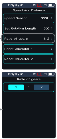
- [Speed Sensor]: Selects the target sensor. If the sensor and receiver are connected, then it will appear in this menu automatically. You can choose between two speeds or [None].
- [Set Rotation Length]: If a speed sensor is installed on the wheel, you need to define the Rotation Length. This length will be used to calculate the distance traveled. Click "+" or "-" to adjust the radius.
- [Ratio of gears]: The gear ratio is the ratio of the number of teeth on the gear that is actually being monitored to the number of teeth on the gear that is targeted for monitoring. When it is inconvenient to install a sensor on the device with the desired rotational speed, you can try testing the rotational speed of the transmission parts and setting an appropriate gear ratio to monitor the speed of this device. Tap [Ratio of gears] to enter, tap the function box, then adjust the value using "+" or "-".
- [Reset Odometer 1]: Odometer 1 is used to record the distance traveled.
- [Reset Odometer 2]: Odometer 2 is used to record the total driving distance, and as such is the cumulative distance from each session.
i-BUS2 Speed Sensor Set
This function is used to set the number of reflective spots on the corresponding sensor.
![Speed Sensor Set screen with Speed Sensor NONE and Reflective Spot 1, and the Select Sensor list with NONE and Motor Speed[57]](/manuals/nb4-plus/screen-speed-sensor-set.png)
- [Speed Sensor Set]: Select the sensor. Click it to enter, then select the sensor. Click the back arrow to return.
- [Reflective Spot]: To set the number of sensor reflective spots. Namely, this value corresponds to the actual number of reflecting points on the device. Click "+" or "-" to adjust the number.
Altitude Zero Set
This function is used to set the current height to 0 m base height.
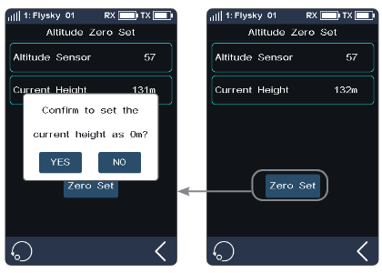
- [Altitude Sensor]: To display the ID of the sensor. If multiple altitude sensors are connected, by default this is the sensor with the smallest ID.
- [Current Height]: Displays the real time height information after performing zero adjustment; otherwise, it is the actual altitude information.
After performing zero adjustment, the height information before and after zero adjustment will be displayed in [Sensor List]. That is, it is height and altitude.
Click the reset icon to reset the current altitude to the actual altitude. After clicking, select [YES] after the prompt box pops up.
GPS Set
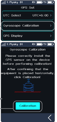
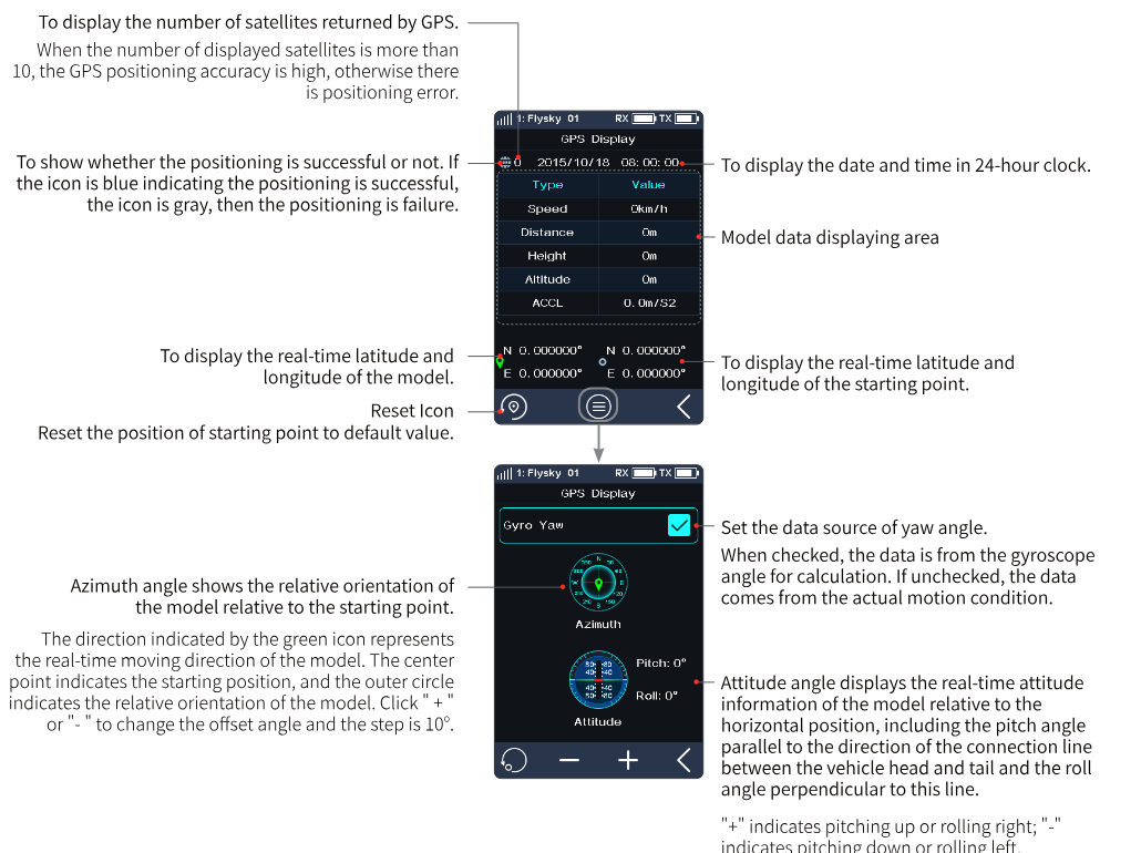
This function is applicable to the GPS module of the i-BUS2 protocol. Through this function, you can set the standard time zone, perform gyroscope level calibration, and view the GPS parameter display interface to get relevant information.
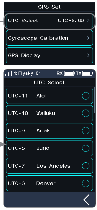
- [UTC Select]: Sets UTC. Tap UTC select to enter, and tap an appropriate time zone. Then click the back arrow to return.
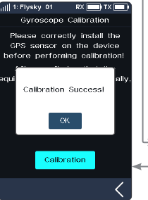
- [Gyroscope Calibration]: Calibrates the gyroscope. Before calibration, please connect the GPS sensor to the device correctly and make sure the device is placed horizontally. Tap Gyroscope Calibration to enter, then click Calibration. The system will calibrate automatically. When calibration succeeds or fails, the system prompts a pop-up screen with the success or failure of calibration. Recalibrate it in case of failure.
[GPS Display]: To display the information returned by the GPS sensor.
Curr and Vol Sensor Set (Current and Voltage Sensor Set)
This function is adapted to i-BUS2 protocol current and voltage sensors, to reset sensor data and related max/min data.
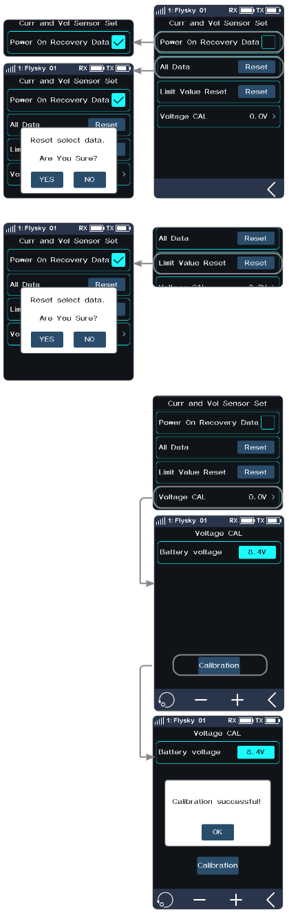
- [Power on Recovery Data]: Sets whether the recorded data will be cleared automatically when the current and voltage sensor is powered on. The recorded data include the maximum/minimum voltage, maximum current, average current, battery consumption capacity, and run time. When the item is ticked, the recorded data will be cleared automatically; otherwise, it will not be cleared.
- [All Data]: Clears all recorded data. The recorded data include the maximum/minimum voltage, maximum current, average current, battery consumption capacity, and run time. Tap [All Data], then select "YES" after the prompt box pops up.
- [Limit Value Reset]: Resets all extreme values, which include the maximum/minimum voltage and the maximum current. Tap [Limit Value Reset], then select "YES" after the prompt box pops up.
- [Voltage CAL]: Calibrates the battery voltage. Note that you must properly connect the sensor's detection line to the device to be detected before starting calibration.
Setup:
- Tap [Voltage CAL] to enter the next level interface.
- Click "+" or "-" to change the value accordingly, then tap [Calibration]; the system prompts that the calibration is successful. Click "OK" to finish the calibration.
6.12CH SPEED
This function allows you to set the steering speed, forward speed, brake speed and response speeds of CH3 to CH8.
Note: The number of channels controlled is subject to the [Channel Number Definition].
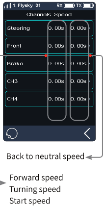
- [Steering]: Changes the corresponding speed of the servo when the steering channel is outputting at fast speed. The minimum delay is 0.00s, and maximum delay is 10.00s. The adjustment step is 0.01s. This function can be used for adjustment when the vehicle is operated with fast steering, which may cause the vehicle to lose control or when the vehicle structure cannot withstand a too fast steering speed.
- [Front]: Sets the response speed of the throttle channel. This function can be used to imitate models with slow acceleration and deceleration response (for example, large trucks).
- [Brake]: Used for vehicle models.
The [Steering Speed Turn], [Steering Speed Ret. (Steering Speed Reset)], [Throttle Speed Go], [Throttle Speed Ret. (Throttle Speed Reset)], [Brake Speed Go] and [Brake Speed Ret. (Brake Speed Reset)] can be adjusted after assigning VR and TR keys or knobs in the [ASSIGN] function. A window will pop up when you adjust the real-time value by keys.
Channel Speed - Steering
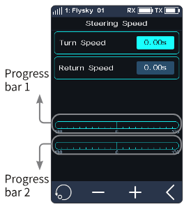
- [Turn speed]: Slows down channel output speed when the steering wheel is moving from the neutral position to maximum travel.
- [Return speed]: Slows down channel output speed when the steering wheel returns to the neutral position.
Setup:
- Click [Turn Speed] or [Return Speed]. This item is highlighted when selected.
- Click "+" or "-" to change response duration as needed.
- Verify that the settings are normal as expected.
Progress bar 1: Shows the channel output speed after the delay. Progress bar 2: Shows the actual speed before the delay takes effect.
Channel Speed - Brake
This function is only applicable to normal mode. This function is not displayed in boat mode.
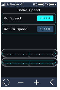
- [Go Speed]: Sets the speed of the throttle brake.
- [Return speed]: Sets the speed at which the throttle brake returns to the neutral position.
Setup: Please refer to Channel Speed - Steering.
Channel Speed - Front
This function is used to set the delay of the throttle start and return-to-neutral.
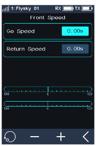
- [Go Speed]: Sets the speed of throttle acceleration.
- [Return Speed]: Sets the speed at which the throttle returns to the neutral position.
Setup: Please refer to Channel Speed - Steering.
Channel Speed - CH3-CH8
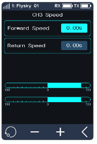
This function is used to set the delay time of CH3-CH8 forward and return-to-neutral.
6.13MIXES
This function allows you to set 3 mixing functions, that is, [4WS Mixing], [Brake Mixing], and [Programming Mixes].
4WS Mixing
Used to set the wheels that control steering of the vehicle: front, rear or all four wheels. This function is applicable to crawlers with steering on both front and rear wheels. By default, the front wheel steering is used in this function.
[Mixing Rate]: Sets the amount of mixing from the steering channel to the mixed channel. The adjustment range is 0-100%.

Setup:
- Click [Ch3] on the right side of [Mixing Channel]. Then click the corresponding channel as needed. After selection, the channel will be occupied. Click the back arrow to return to the previous interface. Each channel can only be assigned one mixing function. It is not allowed to conflict with other Func Assign channels. When the selected channel is assigned with other mixing functions, the system will give a pop-up window reminder.
- Click "+" or "-" to change the rate as required.
- Select the steering type as required. You can select [Steering Mix Mode] in the [Assign] function, and assign SW controls to switch four different functions. Alternatively, you can select [Steering Mix Rear], [Steering Mix Same] or [Steering Mix Reverse], to realize fast switching between this function and [Steering Mix Front] through SW controls.
- Touch the on/off icon to enable this function. When this function is enabled, the icon will change to on.
- Verify the settings are normal as expected.
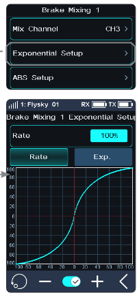
Brake Mixing
This function has two sets of brake mixing controls, to use multiple servos to control brakes; for example, models using different servos to control the front and rear brakes.
If your model uses multiple channels to control the brakes together, you can use this function to control the brake channel as a mixer channel for the throttle channel.
Setup:
- Click [Brake Mixing 1: Off] option to enter the submenu.
- Click [CH3] on the right side of [Mix Channel]. Then click the corresponding channel as needed. This channel will be occupied after selection. Click the back arrow to return to the previous level interface. Each channel can only be assigned one mixing function. It is not allowed to conflict with other Func Assign channels. When the selected channel is assigned with other mixing functions, the system will give a pop-up window reminder.
- Perform the settings by following the steps of setting the [EXP] and [ABS] function.
- Use the servo display function. Verify that the settings are normal as expected.
You can select the menu corresponding to brake mixing in [ASSIGN], and assign VR, TR key or knob for adjustment. A pop-up window will appear to show the real-time value during the adjustment by key. Select [Brake 1 EXPs], [Brake 1 A.B.S.] or [Brake 2 EXP], [Brake 2 A.B.S.] to assign SW controls for fast enable/disable of two sets of brake mixing functions.
Programming Mixes
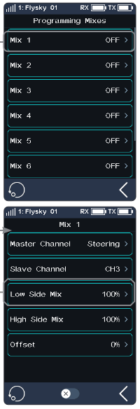
The Mixing function can be used to set the mix-control relationship between channels, containing a total of 8 groups of mixing relationships.
Setup:
- Click [Mix 1] or other mixing options as needed to enter the setting interface.
- Touch the on/off icon to enable this function. When this function is enabled, the icon will change to on.
- Click [Master Channel], select a primary channel from the list. The primary channel will affect the slave channel.
- Click [Slave Channel] and select a slave channel from the list.
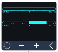
- Select [Low Side Mix] or [High Side Mix] as needed. Click "+" or "-" to change the percentage to adjust the amount of low end or high end mixing. Click the back arrow to return to the menu when the setting is complete.
- Click [Offset]. Then click "+" or "-" to change the offset associated with the master channel and the slave channel.
- Repeat the above operations to set other mixing controls.
Assign VR, TR keys or knobs in the [Assign] function to adjust 8 groups of programmed mixing controls of [Low Side Mixing], [High Side Mixing] and [Offset] rates. A pop-up window will appear in the adjustment by pressing the key, prompting the real-time value. In addition, it is possible to quickly enable or disable Mix 1 to Mix 8 functions by using the SW controls.
6.14TH PROP
Note: This function is available for version 1.0.9 or later.
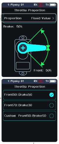
The TH PROP (throttle proportion) function is used to set the neutral position of the throttle and brake to correct the problem of unequal throttle travel and brake travel of some models. If the neutral position is not set correctly, the model may start acceleration and driving directly after power-on.
[Proportion]: You can choose a fixed rate (Front 50: Brake 50, Front 70: Brake 30) or a custom rate.
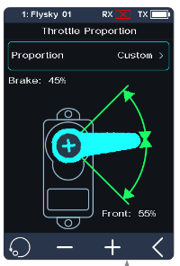
Setup:
- Tap [Proportion] to enter.
- Click an appropriate item, then click the back arrow to return to the previous interface. If Custom is selected, click "+" or "-" to change the percentage as desired after returning to the previous interface.
- Verify the settings are normal as expected.
6.15TH NEUTRAL
The function is used to set a "dead zone" for throttle control, in which the throttle always outputs the neutral value, and the throttle channel does not change when moving the trigger.
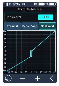
- [Forward]: When it exceeds the dead zone, the throttle channel will output this value directly to accelerate forwards.
- [Dead Zone]: The range of the dead zone. By default, the value is 0%.
- [Backward]: When it exceeds the dead zone, the throttle channel will brake or output this value directly to accelerate backwards.
Setup:
- Touch [Forward], [Dead Zone] or [Backward]. This item is highlighted when selected.
- Use "+" and "-" to change the percentage as needed.
- Repeat with other settings as needed.
- Test to make sure everything works as expected.
6.16TH CURVE
The throttle curve function is used to adjust the response speed of the throttle at different positions. By default, it is disabled and the throttle curve is output linearly.
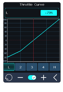
Setup:
- Assign a switch for throttle curve in the function of [ASSIGN].
- Touch the on/off icon to enable this function. When this function is enabled, the icon will change to on.
- Touch a point. When selected, the option will be highlighted.
- Use "+" and "-" to raise or lower the point's position as needed.
- Repeat for the other points as needed.
- Test to make sure everything is working as expected.
6.17IDLE UP
Throttle Idle Up is used for models that use a fuel based engine that will stall if left at 0 throttle. Idle up makes sure that the engine always has some throttle in order to keep it from stalling.
This function must be assigned to a control in order to be activated.
This function will reset after shutting down. You need to restart this function after turning on again.
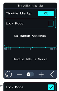
Setup:
- Assign a switch for idle up in the function of [ASSIGN].
- Touch the on/off icon to enable this function. When this function is enabled, the icon will change to on.
- Click "+" or "-" to change the percentage as needed.
- Test to make sure everything is working as expected.
6.18ENG CUT
When Engine Cut is triggered via a button it sets the throttle channel to a predefined position.
This function must be assigned to a switch/button in order to be activated.
This function will reset after shutting down. You need to restart this function after turning on again.
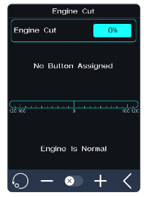
Setup:
- Assign a switch for engine cut in the function of [ASSIGN].
- Touch the on/off icon to enable this function. When this function is enabled, the icon will change to on.
- Click "+" or "-" to change the percentage as needed.
- Test to make sure everything is working as expected.
6.19CRUISE
When the cruise function is enabled, the throttle channel keeps the channel value output as when the function was enabled. When the vehicle travels at the desired speed, the cruise function can be enabled. The vehicle can continue to travel at the same speed after it is enabled, but you can also manually increase the speed.
[Manual Acceleration]: When this function is enabled, pulling the trigger can increase the throttle amount in the cruise state, and the vehicle accelerates. When the trigger is released, the vehicle can continue to travel at the previous speed.
The function interface displays the percentage of throttle channel output value in real time.
Pull the trigger or toggle the assigned control to exit cruise state.
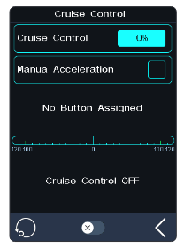
Setup:
- Assign a switch to enable or disable the function via ASSIGN function. When this function is enabled, the icon will change to on. Assign SW controls to enable/disable the cruise function quickly. A pop-up window will appear, indicating the current status.
- Click "+" or "-" to change the percentage as needed. Assign TR controls to adjust the value of the fixed speed cruise. A pop-up window will appear in the adjustment by pressing the key, prompting the real-time value. And when SW2 and SW3 are in the state of key combination, they can also be assigned to adjust the value of cruise. The percentage cannot be adjusted when the cruise function is not enabled.
- Click [Manual Acceleration], increase the throttle as needed. The throttle capacity can be increased through the trigger. After releasing the trigger, the throttle will return to the set value.
6.20BOAT
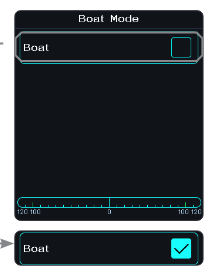
This function is used only when you are using a model boat. When this function is active, the throttle channel is set to its lowest position and the brake functionality is disabled.
To enable this function, select [Boat] to switch to boat mode. When switching is successful, [Normal Mode] is changed to [Boat Mode]. The check box is selected.
6.21DISPLAY
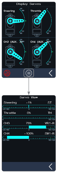
This function displays the model's channel output and can be used to test output and servo range.
Press the test icon to start servo test mode, which will move all the channels slowly through their entire range of motion. Press it again to turn off servo test mode.
- Make sure the model engine is powered off while the test function is activated.
Click the list icon to enter the channel display interface. In this list, you can view the data progress bar of all channels and the percentage data of channels.
6.22BEGINNER
The beginner mode is suitable for entry level players to improve the safety of operations by limiting the amount of throttle servo.
This function is hidden by default. You need to enable it manually.
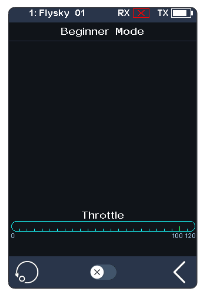
Setup:
- Go to the [Custom Main Menu] menu under the [MODEL] menu bar, and select the [Beginner] check box. After selection, this function is displayed on the menu interface.
- Find the function in the menu and touch the on/off icon to enable this function. When this function is enabled, the icon will change to on.
Assign SW controls to enable/disable the beginner function.
6.23SVC
The receivers configured with this function are INr4-GYB (built-in gyroscope) and GMr (with gyroscope interface).
After the transmitter has bound with the receiver in AFHDS3 2 Way mode, press the SVC to access the function, coming along with a prompt for gyroscope level calibration. It is recommended that the user should follow the prompt on the interface to complete the gyroscope calibration when using the gyroscope for the first time.
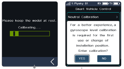
Assign SW controls to quickly enable/disable the SVC function. Assign VR/TR controls to quickly adjust Steering Gain, Throttle Gain, Priority, and Advanced functions such as ST Wheel Gain, Damper Point, Damper, and Filter. Assign SW controls to quickly switch between model vehicle types.
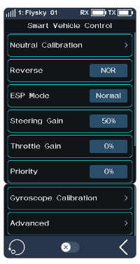
Neutral Calibration
Used for the gyroscope to calibrate steering and throttle neutral to make the best driving condition when the vehicle is driving normally. Before enabling the SVC function, you need to adjust the vehicle's steering servo volume, neutral trim and throttle neutral to the best driving condition. After completion, start the [Smart Vehicle Control] function for neutral calibration. Every time you change the trim or throttle curve, you need to calibrate the neutral position. The steering and throttle should be placed in the neutral stationary state during the calibration process.
Reverse
You can set the direction when the gyroscope mixes with the steering channel.
ESP Mode
Used for model assisted stability. Two modes are available: normal/lock.
- [Normal]: When the vehicle is yawing or steering, the gyroscope automatically provides an opposite compensation to control the servo to keep it stable or prevent drifting according to the angular velocity generated.
- [Lock]: If the steering wheel is returned to center, the gyroscope will control the servo in the opposite direction according to the yaw angle when the vehicle is yawing, to make it go back to the expected direction (if the steering wheel is not returned to center in the "Lock mode", it will be the same as the "Normal mode").
Steering Gain
Used to change the sensitivity of the mixing steering channel.
Throttle Gain
Used to change the sensitivity of the mixing throttle channel.
Priority
Used to set the control ratio between steering wheel control and gyroscope in the steering, i.e., turning radius. In direction turning by using the steering wheel, the steering angle will be reduced due to the influence of gyroscope mixing. When the value is 0%, the mixing control is the strongest, that is, the turning radius is the largest. When the value is 100%, the mixing control is 0, that is, the turning radius is the smallest.
Gyroscope Calibration
Used for the first time to enable the gyroscope via binding or gyroscope calibration required after replacement. The model keeps a stable and stationary state. Click calibration. The receiver flashes twice and exits automatically. This indicates that the calibration is successful.
(The above are the adjustable parameters when the transmitter is adapted to the GMr receiver and FS-GY01 gyroscope, and they are also adjustable when it is adapted to the INr4-GYB receiver.) Note: The Advanced function was added for 1.0.2 version firmware.
Advanced
To adapt the INr4-GYB receiver to model drift cars, etc. You can set the type of the model car, and customize parameters for [ST Wheel Gain], [Damper Point], [Damper] and [Filter].
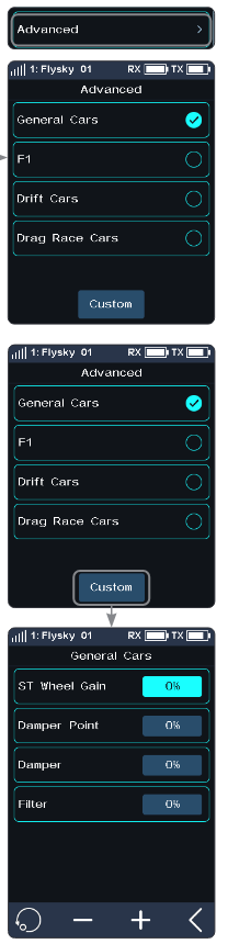
- [ST Wheel Gain]: Adjustment of the intervention ratio of steering operation to gyro control. It is more sensitive in the steering control when the value increases.
- [Damper Point]: Adjusts the servo to the damper point in front of the target angle position. In the damping interval, the servo oscillation speed will be slowed down. The higher the value, the larger the interval in which the servo speed is slowed down.
- [Damper]: Slows down the servo speed in the damper point, and adjusts the damping effect in the damper point. The higher the value, the slower the servo slowing down in the damper point. As a result, it takes longer for the servo to reach the target angle. This parameter needs to be set together with [Damper point] to achieve the best result.
- [Filter]: Used to suppress jitter. The higher the value, the stronger the jitter suppression.
Setup:
- Tap the on/off icon to enable this function. When this function is enabled, the icon will change to on. If the gyroscope is not connected, this function cannot be activated, and the system prompts "The current receiver is not properly connected to the gyroscope".
- Click [Neutral calibration]. A pop-up box will appear: "Are you sure you want to enter neutral calibration? Put the steering and throttle in the neutral stationary state before entering". Click "Yes". The transmitter enters the calibration state. The system prompts successful calibration with a sound reminder.
- If you want to change the direction of action, please click [Reverse]. If the function is set to reverse, it will show "Reverse". The method of changing ESP is the same as above.
- Under this function, you can also set the percentages of [Steering Gain], [Throttle Gain], and [Priority]. The adjustable percentage range is 0% to 100%. After selecting the option, click "+" or "-" to change the percentage.
- Click [Gyroscope calibration]. A pop-up box will appear, indicating "Are you sure you want to start the calibration". The system prompts successful calibration with a sound reminder. When calibrating the gyroscope, please make sure the model is in a stable and stationary state.
- Tap [Advanced], then select a type for the model car. After clicking [Custom], tap an item you want to set. Afterwards, click "+" or "-" to set to the desired value.
6.24TRAINER
Noble NB4+ supports three function modes: Trainer, Student and H Track. Transmitters set to Trainer or H Track Mode accept external signals to control the model, that is, the trainer interface or head tracker interface has the ability to recognize external PPM signal input. Transmitters set to Student Mode only output PPM signals and do not recognize the input signals.
Two transmitters (one for Trainer mode and one for Student mode) can be connected via a double-ended Type-C cable to realize the coach function.
One transmitter (H Track mode) can be connected to the headset via head tracker cable to realize the head tracker function.
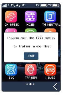
Setup:
- Find this function in the menu and touch the on/off icon to enable this function. When this function is turned on, the icon will change to on. You can assign a control in the [ASSIGN] interface to enable or disable this function.
- Click Mode (it is Trainer by default) to switch to Student and H Track.
- Perform the test to ensure that the settings work as intended.
When the trainer and student transmitters are properly connected, the relationship between the control switch states for the student and trainer and the actual control source is shown in the table below.
| Trainer Switch | Student Switch | Actual Control |
|---|---|---|
| ON | ON | Trainer |
| ON | OFF | Trainer |
| OFF | ON | Student |
| OFF | OFF | Trainer |
If there is an abnormal connection between the trainer and student transmitters, then the actual control source is the trainer transmitter.
Trainer
When the Trainer Mode is set to Trainer, the transmitter only supports the Trainer function at this time.
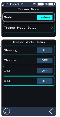
Setup:
- Click to enter [Trainer].
- Click [Trainer Mode Setup] to select to turn on [Steering], [Throttle], [CH 3-8]. The number of channels displayed is based on [Channel Number Definition] in [MODEL].
- Perform the test to ensure that the settings work as intended.
Click the reset icon to reset the Trainer Mode function. If you select [Yes] in the pop-up window, all settings are restored to the default values. If you select [No], the pop-up window closes directly.
Student
When the Trainer Mode is set to Student, the transmitter only supports the Student function at this time.
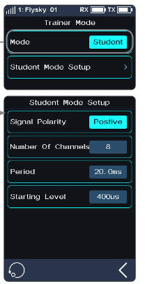
- [Signal Polarity]: High level is valid by default (positive). Some devices may recognize low level as a valid signal. At this time, set the signal polarity to negative, that is, low level is valid.
- [Number of Channels]: Set the number of channels in a PPM signal. By default, a PPM signal contains 8 channels. The setting range is 4-8, and the step is 1.
- [Period]: Refers to the time of transmitting a PPM signal. The standard 8-channel PPM signal period is 20ms. The range is 12.5 - 45ms, and the step is 0.5ms. When fewer channels are used, a shorter period can be set to shorten the time required to send a signal to reduce latency. However, the setting of the period can only shorten the idle period, instead of the effective signal duration. Therefore, the setting of the period will not reduce the number of signal channels. When the number of channels increases and the effective signal sending time is greater than the period, the system will process the signal in the minimum idle mode, and the interface setting value will not be changed accordingly.
- [Starting Level]: The start mark time identifies the PPM signal. Default value is 400us. The range is 100 - 700us, and the step is 50us.
Setup:
- Click to enter [Student].
- Click [Signal Polarity] to switch to negative (low level is valid). Some devices may recognize a low level as a valid signal, and at this time [Signal Polarity] should be switched to negative.
- Click [Number of Channels], [Period] or [Starting Level]. When selected, this item is highlighted.
- Click "+" or "-" to change the number of channels, period or starting level as needed. Long press "+" or "-" to accelerate the adjustment of the corresponding values.
- Perform the test to ensure that the settings work as intended.
Click the reset icon to reset the Student Mode function. If you select [Yes] in the pop-up window, all settings are restored to the default values. If you select [No], the pop-up window closes directly.
H Track
When the Trainer Mode is set to H Track, the transmitter only supports the Head Tracker function at this time.
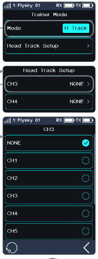
Setup:
- Click to enter [H Track].
- Click the corresponding channel in the list to assign (by default, it is unassigned). You can assign CH1-CH8 as the control channels. The number of channels displayed is based on [Channel Number Definition] in [MODEL].
- Perform the test to ensure that the settings work as intended.
Click the reset icon to reset the Head Tracker Mode function. If you select [Yes] in the pop-up window, all settings are restored to the default values. If you select [No], the pop-up window closes directly.
Notes:
- Users need to prepare the cable for the Trainer function (dual-ended Type-C cable) and the cable for the Head Tracker function (Type-C port on one end and audio port on the other end) in advance. If users do not have a suitable head tracker cable, the FS-XC201 Type-C cable can be used to change the cable according to the definition of the Type-C cable sequence, retaining the Type-C connector of the Type-C cable. Use pliers or other tools to cut off the other end of the Type-C cable, and lead out the wire cores wrapped by the Type-C cable. The user confirms which two wires are the ground line (GND) and the signal line (PPM). Generally, the black wire core is the ground line and the white wire core is the signal line. It is subject to the actual measurement of the wire sequence. Take the S-terminal of the head tracker interface as an example. Before rewiring, you need to confirm the pin definition of the S-terminal, so as to lead out the earth wire (GND) and signal wire (PPM) wrapped in the head tracker cable. The steps are similar to those of rewiring the FS-XC201 Type-C cable. Keep the S-terminal connector of the head tracker cable, cut off the other end with pliers or other tools, and lead out the cores wrapped in the head tracker cable, and then connect the two cores of the FS-XC201 Type-C cable with the two cores of the head tracker cable. Then you can use the head tracker function normally (the GND line connects to the GND line, and the signal line connects to the signal line). Take the 3.5mm head tracker interface as an example. Choose the 3.5mm Type-C cable to change to a 3.5 mm audio port adapter cable. You need to confirm in advance whether the audio port of the FPV glasses outputs PPM signals (for details, check the FPV glasses manual). Meanwhile, make sure that the signal line (PPM) of the Type-C cable connects to the PPM signal line of the audio port. If the connection is not established, the transmitter will not be able to correctly identify the PPM signal output from the headset, and will not control the headset.
- Before enabling this function, you need to select Trainer Mode by choosing [System] > [USB Setup].
- To enable the Trainer function, short press the power button of both transmitter bases to make sure that the bases of both transmitters are activated. Meanwhile, make sure that the two transmitters are connected correctly. To realize the head tracker function, short press the power button of one transmitter base to make sure that the base of the transmitter is activated, and make sure that the headset is connected correctly.
- The Noble NB4+ Trainer Interface of the transmitter can adaptively identify the input PPM signals. Most of the devices that support PPM output can be used as the external input signal source of the Trainer Mode. However, some of the devices may not support this function, and you can set up the PPM output of the Trainer Interface to match the external devices that have the special requirement of identifying the PPM signal.
- When the Trainer transmitter does not detect the Student transmitter, for example, the Student transmitter is turned off or the cable of the Student transmitter is disconnected, the control right is automatically returned to the Trainer transmitter.
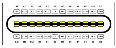
6.25i-BUS2
The i-BUS2 device settings function is used to set up the i-BUS2 devices, such as the FS-iBH07 Hub or i-BUS2 protocol servos.
- At the transmitter side, you firstly need to set the receiver interface to be connected to the i-BUS2 device as i-BUS2 via [RX interface protocol] function.
If the transmitter is normally connected to the i-BUS2 HUB, you can set it as a PWM converter. If the transmitter is normally connected to an i-BUS2 sensor type device, you can access the sensor setting interface through this function. If the transmitter is normally connected to an i-BUS2 type servo or ESC, you can set the relevant function parameters, monitor data, and assign channels for controlling devices.
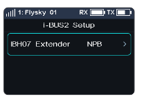
FS-iBH07 Extender
When the transmitter detects the i-BUS2 HUB device, the i-BUS2 HUB device can be set as a PWM converter or reset back to the i-BUS2 HUB device via this function.
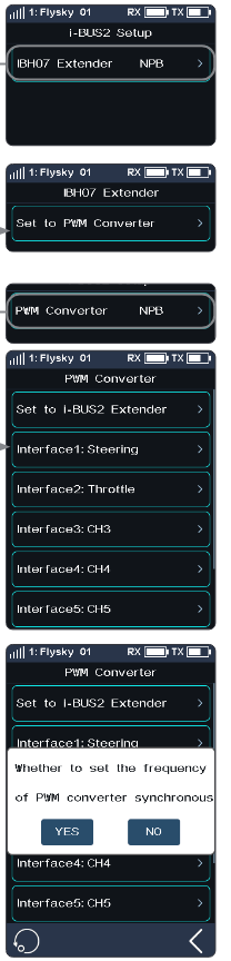
Setup:
- Click [i-BUS2 Setup] to enter the setting menu.
- Tap [iBH07 Extender NPB].
- Click [Set to PWM Converter]. After clicking [OK] in the pop-up window, tap [PWM Converter NPB].
- Tap [Set to i-BUS2 Extender] to set it back to HUB. Or tap one interface to enter, then click a channel to set as the output channel of the converter.
- Tap the back arrow to return; a prompt pop-up window comes along with it: "Whether to set the frequency of PWM converter synchronous". Then click [YES] or [NO] to exit. If you select YES, it will be synchronous; otherwise not.
- The voltage returned from the extender can be displayed in real time in the [Sensor] menu.
- When a servo is connected to an interface set to i-BUS2 protocol, it will display the servo type and the interface in the [i-BUS2 Setup] menu.
i-BUS2 SENSOR
When the transmitter detects an i-BUS2 sensor, you can set the function parameters of the sensor in this function. Refer to 6.11 SENSOR for more details.
i-BUS2 SERVO (FXS260/380)
When the transmitter detects the i-BUS2 FXS260/380 servo, you can use this function to set the relevant function parameters of the servo, monitor the information returned from the servo, and assign the channel for controlling the servo.
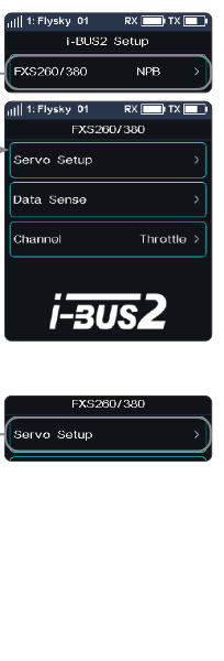
Servo Setup
Set the function parameters to adjust the corresponding servo.
- [Soft Start]: Sets the response speed of the servo's instant startup.
- [Thermal Protection]: Enables/disables the thermal protection function of the servo.
- [Power]: Sets the output power of the servo when it is working.
- [Boost]: Sets the voltage of the servo's instant startup, so as to change the startup strength of the servo.
Setup: Select the function item, then click "+" or "-" to change the percentage or the option.
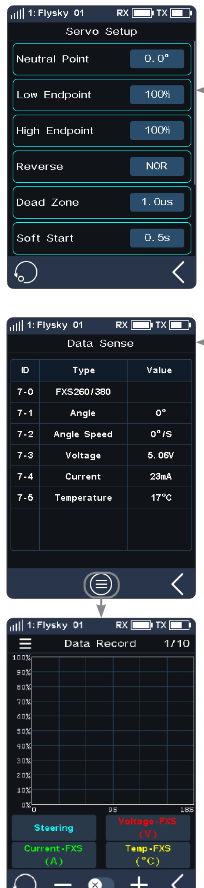
Data Sense
Monitor the return information from the corresponding servo. Tap [Data Sense] to enter the Data Sense interface. You can also tap the list icon to enter the Data Record interface.
Note: If the sensor data record has been set to display information related to this i-BUS2 servo, then click to enter the data recording interface. Otherwise, a pop-up window will prompt whether to switch to the information about the device. Click YES to switch, click NO not to replace, and the original device information will still be displayed.
Channel
Assign the corresponding channel to control this servo. Tap [Channel: Steering] to enter, then tap an appropriate channel. Afterwards, click the back arrow to return to the previous interface.
i-BUS2 SERVO (Power HD)
When the transmitter detects an i-BUS2 servo (Power HD), you can use this function to set the relevant function parameters of the servo, monitor the information returned from the servo, and assign the channel for controlling the servo.
The settings of Power HD servo parameters are similar to those of the FXS260/380. Refer to the description of FXS260/380 servos. You can save Power HD servo parameters as two sets of configuration parameters. Two sets of commonly used parameters can be saved as Configurations 1 and 2, respectively. Both can be switched by setting a control.
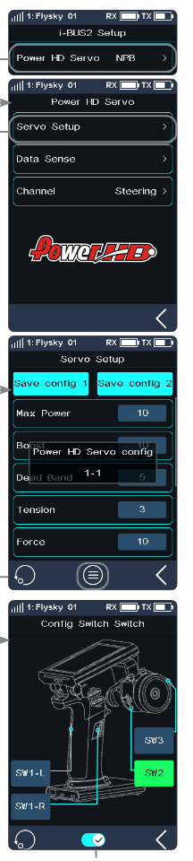
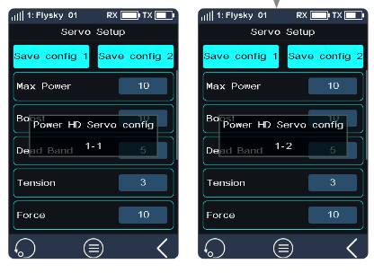
Setup:
- Two sets of commonly used parameters can be set and saved as Configurations 1 and 2 by tapping Save config 1 or Save config 2, respectively.
- Tap the list icon to enter the Config Switch interface.
- Select a control, then tap the on/off icon to enable this function. When this function is enabled, the icon will change to on. Then the two sets of configurations can be switched by this control.
Click the reset icon to reset the settings to the default data, that is, the data of Configuration 1. If the data of Configuration 1 is not set when you click to reset the data, the system prompts to save the data of Configuration 1 first.
About the setting of the Power HD servo on Data Sense and Channel, refer to the description of FXS260/380 servos.
Note: For details about Power HD parameters, see the corresponding manual of the Power HD servo.
i-BUS2 SERVO
When the transmitter detects an i-BUS2 servo, you can use this function to set the relevant function parameters of the servo, monitor the information returned from the servo, and assign the channel for controlling the servo.
The settings of i-BUS2 servo parameters are similar to those of the Power HD. Refer to the description of Power HD and FXS260/380 servos.
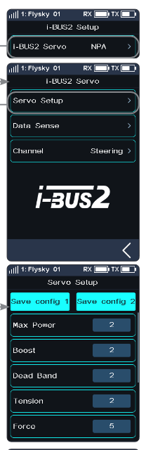
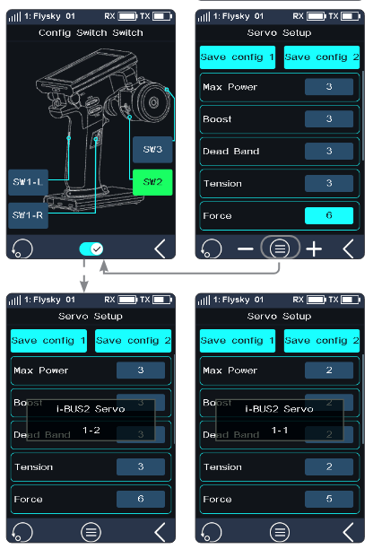
About the setting of the i-BUS2 servo on Data Sense and Channel, refer to the description of FXS260/380 servos.
Note: For details about i-BUS2 parameters, see the corresponding manual of the i-BUS2 servo.
i-BUS2 ESC (XERUN AXE R2)
When the transmitter detects an i-BUS2 XERUN AXE R2 ESC, you can use this function to set the relevant function parameters of the ESC.
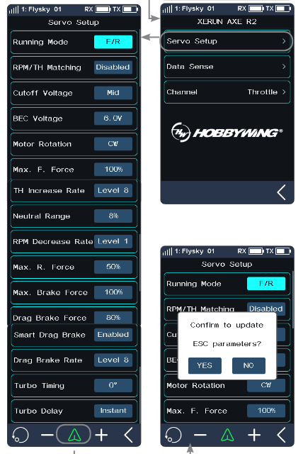
Servo Setup
Set the function parameters to adjust the corresponding ESC.
Setup: After selecting the function item to be set, click "+" or "-" to adjust the value or option; click the send icon and then click [Yes] to send the set parameters to the ESC device, which will take effect after the ESC is restarted.
Notes:
- The RPM Decrease Rate can be set only when the RPM/TH Matching is set to Disabled.
- For details about ESC parameters, see the corresponding manual of the ESC.
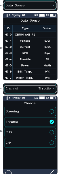
Data Sense
Monitor the return information from the corresponding ESC. Tap [Data Sense] to enter the Data Sense interface. You can view the relevant information. You can also tap the list icon to enter the Data Record interface.
Note: If the sensor data record has been set to display information related to this i-BUS2 ESC, then click to enter the data recording interface. Otherwise, a pop-up window will prompt whether to switch to the information about the device. Click YES to switch, click NO not to replace, and the original device information will still be displayed.
Channel
Assign the corresponding channel to control this ESC. Tap [Channel: Throttle] to enter, then tap an appropriate channel. Afterwards, click the back arrow to return to the previous interface.
i-BUS2 ESC (XERUN AXE R3)
Note: This function is available for version 1.0.7 or later.
When the transmitter detects an i-BUS2 XERUN AXE R3 ESC, you can use this function to set the relevant function parameters of the ESC.
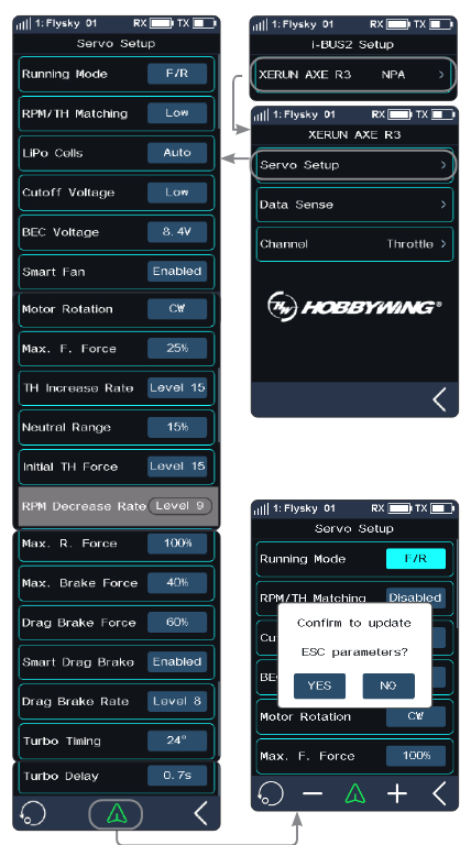
Servo Setup
Set the function parameters to adjust the corresponding ESC.
Setup: After selecting the function item to be set, click "+" or "-" to adjust the value or option; click the send icon and then click [Yes] to send the set parameters to the ESC device, which will take effect after the ESC is restarted.
In addition, for [Max. F. Force], [TH Increase Rate], [RPM Decrease Rate], [Max. R. Force], [Max. Brake Force], [Drag Brake Force], [Drag Brake Rate], [Turbo Timing], and [Turbo Delay], you can also adjust the parameters in real time (parameters are not saved) by using the VR/TR type controls assigned by the [ASSIGN] function. However, in this functional interface, it cannot be adjusted through VR/TR controls. It can be adjusted through VR/TR controls in other interfaces, and a pop-up window will appear to prompt the real-time adjusted value. Note that when adjusting [Drag Brake Force] through the control, the adjustment range is the same as the range set through [Servo Setup].
Notes:
- The RPM Decrease Rate can be set only when the RPM/TH Matching is set to Disabled.
- For details about ESC parameters, see the corresponding manual of the ESC.
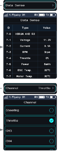
Data Sense
Monitor the return information from the corresponding ESC. Tap [Data Sense] to enter the Data Sense interface. You can view the relevant information. You can also tap the list icon to enter the Data Record interface.
Note: If the sensor data record has been set to display information related to this i-BUS2 ESC, then click to enter the data recording interface. Otherwise, a pop-up window will prompt whether to switch to the information about the device. Click [YES] to switch, click [NO] not to replace, and the original device information will still be displayed.
Channel
Assign the corresponding channel to control this ESC. Tap [Channel: Throttle] to enter, then tap an appropriate channel. Afterwards, click the back arrow to return to the previous interface.
6.26LAMP
Note: This feature was added in version 1.0.17.
This feature is only compatible with the INr8-8D receiver. When the system detects a successfully bound INr8-8D receiver in AFHDS 2 Way, this menu option becomes accessible for configuring LED light parameters.
After successful two-way binding between the transmitter and the INr8-8D receiver, you can switch between three preset light configurations: config 1, config 2, and config 3. The default display shows the currently active configuration on the receiver. For detailed information about these configurations, please refer to the INr8-8D receiver manual.
The transmitter allows customizing specific settings under all three configurations, including the corresponding lamp assignments, modes, luminance, channels, trigger values, control effect for each LED light interface, and one-button closing mode for all interface lights.
Tap [LAMP] to enter.
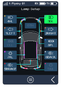
The interface permanently displays 10 commonly used "Lamp Buttons" (Left Turn Light, Right Turn Light, Day Light, Headlights, Brake Light, Backup Light, Ambient Light, Fog Lamp, Clearance Lamp, and Tail Light), while other lights will be shown in the secondary interface.
When a displayed light is assigned to a specific receiver interface, the corresponding "Lamp Button" will show its assigned interface number. If the LED light is active, the button appears highlighted (e.g., "3 DL" in the figure); otherwise, it remains dimmed (e.g., "1 LEFT" in the figure). Tap any "Lamp Button" to enter its interface configuration interface.
If the LED light name on a "Lamp Button" appears grayed out (e.g., "TAIL" in the figure), it indicates that the lamp is unassigned to any specific interface and cannot be clicked.
Configuration Switching
Used to switch between lighting configurations. Cycles sequentially through config 1, config 2, and config 3.
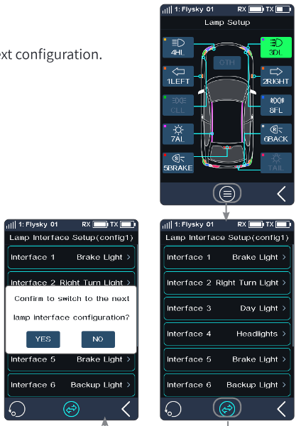
Setup:
- Tap the list icon to enter the Lamp Interface Setup interface.
- Tap the switch icon, click [YES] on the pop-up interface to switch to the next configuration.
Custom Config 1 Settings
For custom configuration 1 settings. It supports the setup of 8 LED light interfaces (the INr8-8D receiver is equipped with 8 LED light interfaces). It allows for the allocation of LED lights to each interface, followed by relevant settings for the LED lights, as well as the ability to turn on or off all interface lights with one button.
- [Linkage]: When the mode is set to Linkage, you can configure when the LED lights turn on and off, as well as the conditions that trigger these actions, such as light luminance, channel, trigger values, and control effect. Additionally, for brake light and backup light, you can also set the brake functionality settings.
- [Constant]: When the mode is set to Constant, the LED light is in a constantly-on state, and only the luminance of the LED lights can be adjusted.


Setup:
- Set Interface 1 to Interface 8, taking Interface 1 as an example: Click on the [Interface 1] function item to enter the settings interface. Setting the LED light: Click on the [Light] function item to enter the settings interface, select the appropriate LED light option and then click the back arrow to return to the previous interface. Setting the mode: Click on the [Mode] function item to switch options. The default mode is [Linkage], which can be switched to [Constant]. Setting the luminance: Click on the [Luminance] function item and tap "+" or "-" to adjust the luminance value. Setting the channel (when the mode is set to linkage): Click on the [Channel] function item to enter the settings interface, select the appropriate channel option and then click the back arrow to return to the previous interface. Note that when the control channel is set to another channel, not CH1 or CH2, if the channel has already been assigned a control, the corresponding control will be displayed; otherwise, [None] will be displayed. Clicking on the control or [None] will allow you to enter the [Controls Assign] interface to assign a control. Setting the trigger value (when the mode is set to linkage): Click on the function box to the right of "TGR Val." and tap "+" or "-" to adjust the value. Setting the control effect (when the mode is set to linkage): Click on the [Control Effect] function item to cycle through the control effect options. Note that when the control effect is set to [Breathe], luminance adjustment is not available. Setting the brake setup (when the LED light is set as a backup light or brake light and the mode is set to linkage): When the LED light is set as a brake light, click on the [Brake Setup] function item to enter the settings interface. You can choose between [F/R] and [F/R with Brake]. The default mode is [F/R], in which case you can set the [Drag Brake Setup], that is, whether the brake light should be on during drag braking. Simply click on the appropriate option. If you select [F/R with Brake], the brake light will be on when the brakes are applied. When the LED light is set as a backup light, click on the [Brake Setup] function item to enter the settings interface. You can choose between [F/R] and [F/R with Brake]. Note that the motor operation mode set here will synchronously modify the brake setup in the brake light interface. When choosing [F/R] or [F/R with Brake], the illumination status of the backup light and brake light is as follows: Taking control channel CH2 as an example, if [F/R] is selected, when the throttle trigger is pushed forward, the backup light will turn on, and the brake light will illuminate or not based on the drag brake setups. If [F/R with Brake] is selected, when the throttle quickly switches from forward to reverse, it will trigger braking (i.e., the brake light will turn on), and only when the throttle is pushed forward from the neutral position will the reverse action be executed, meaning the backup light will turn on.
- Set the one-button closing mode. By clicking a screen function item or a control (only SW-type controls), all LED lights can be turned off simultaneously. When the LED lights are turned off via a control, a floating window prompt will appear. Setting the screen function item to turn the LED lights on and off: Click on [One-button close]. If checked, all LED lights will be turned off; if unchecked, they will not be turned off. Setting a control to turn the LED lights on and off: Click on [Control: None] to enter the Controls Assign interface; click on a control (e.g., SW1-L) to enter the settings interface; click on the function to enter the function settings interface, scroll down the screen, select the [One-Touch Light Off] function, and then click the back arrow to return to the previous interface; then you can refer to 6.8 ASSIGN to set the [Mode] and [Direction] of the control. Click the back arrow to return.
- Test whether the LED light setups for config 1 meet the expectations.
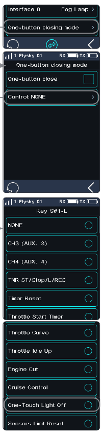
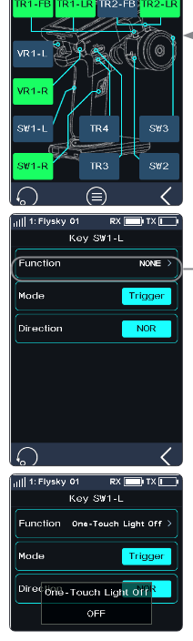
The setup steps for config 2 and config 3 can refer to the settings for config 1.
Restore the configuration
Used to restore the current configuration of the LED light interface (config 1, config 2, or config 3) to the default settings.
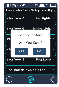
Setup:
- Click on the list icon to enter the LED light interface settings interface.
- Click on the switch icon to switch to the configuration you want to reset.
- Click on the reset icon and then click [YES] on the pop-up interface to restore the current configuration to the default settings.
6.27HELP
To obtain the user manual via this function. Users can contact us through the social accounts listed on the interface.
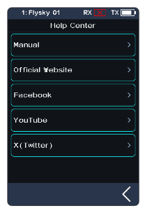
Setup:
- Touch [Help center] to enter.
- Touch the item you want to view, then the corresponding QR code will display.
- Scan the QR code to obtain the related information. Then click the back arrow to return to the previous interface.
7RX SET
This section introduces details of the functions related to the receiver and their use.
7.1Bind Set
This function is used to put the transmitter into the binding state to bind with the receiver. For specific binding guidelines, see section 4.2 Binding.
7.2Steering Force
This function is used to adjust the amount of steering force when the receiver servo is steered.
This function can be set when the transmitter RF Setting is set to [Mini-Z(FHSS)]. It is hidden when the RF is set to other standards.
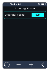
Setup: Click "+" or "-" to change the percentage of steering force. The adjustment range is 0-100%, and the adjustment step is 1%. It can also be adjusted by assigning a TR/VR key or knob in the [ASSIGN] function.
7.3Gyro Gain
This function is used to adjust the sensitivity of the gyroscope on the receiver.
This function can be set when the transmitter RF Setting is set to [Mini-Z(FHSS)]. It is hidden when the RF is set to other standards.
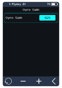
Setup: Please refer to 7.2 Steering Force.
7.4RX Interface Protocol
Note: This function was updated in version 1.0.22.
This function is used to set the receiver output mode.
Classic Edition Receiver Interface Protocol
When the adapted receiver is FGr4, FGr4S, FGr4P, FTr4, FTr10 or FTr16S, the output protocols of [CH1 Interface] and [Serial] can be set respectively. [CH1 Interface] can be set to PWM or PPM. [Serial] can be set to i-BUS or S.BUS (please refer to 7.8 i-BUS Setup for specific i-BUS setting).
- [CH1 Interface]: Sets the output protocol of CH1.
- [Serial]: Sets the output protocol of the serial interface.
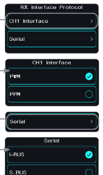
Setup:
- Click [CH1 Interface] or [Serial].
- Tap the corresponding protocol. Click the back arrow to return to the previous level interface.
Enhanced Edition Receiver Interface Protocol
When the adapted receiver is an enhanced edition receiver, the output protocol of the receiver NPA/NPB/NPC/NPD interface can be set.
In dual receiver mode, the interface protocols of the Master and the Slave receiver can be set respectively.
For the NPA/NPB/NPC/NPD interface of the Master receiver, the output modes include PWM, PPM, S.BUS-IN, S.BUS, i-BUS in, i-BUS out, i-BUS2, and i-BUS2-IN. The output modes for the Slave receiver NPA/NPB/NPC/NPD interface are PWM, PPM, S.BUS-IN, S.BUS, i-BUS out, i-BUS2, and i-BUS2-IN.
Pay attention to the following:
- Only one Newport interface can be set as PPM, S.BUS, S.BUS-IN, i-BUS2-IN, i-BUS out, or i-BUS in (with the exception that the slave receiver cannot use i-BUS in).
- The simultaneous conflict of i-BUS and i-BUS2 transmission information is prohibited. When any Newport is set to i-BUS out or i-BUS in, other Newports should not be set to i-BUS2. If any Newport is set to i-BUS2, other Newports should not be set to i-BUS out or i-BUS in.
- Once any Newport interface is set to i-BUS2-IN, other interfaces cannot be set to S.BUS-IN, and vice versa.
- [i-BUS in]: Connects to an i-BUS sensor.
- [i-BUS out]: Connects to an i-BUS Serial Bus Receiver or other i-BUS signal recognition device.
- [i-BUS2]: Connects to an i-BUS2 sensor or other i-BUS2 signal recognition device.
- [i-BUS2-IN]/[S.BUS-IN]: Used to implement signal redundancy functionality.
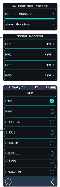
Setup:
- Click [Receiver Interface Protocol]. When the bind setting is in dual receiver mode, select the Master receiver or the Slave receiver to enter the submenu.
- Select [NPA] or other options. Click the corresponding protocol as needed. Then click the back arrow to return to the previous level interface.
Signal Redundancy Feature (i-BUS2-IN/S.BUS-IN) Introduction
When the Newport connector protocol of the receiver is set to i-BUS2-IN or S.BUS-IN, the receiver will have signal redundancy functionality. This allows the receiver to receive signals input through the i-BUS2-IN or S.BUS-IN protocol connectors, and after performing redundancy judgment, it can select to use these signals to control the device. This feature ensures that the controlled device can be operated by the signal with the lowest delay, the best signal quality, or the one that is not out-of-control.
A receiver with redundancy functionality is denoted as RX1, and the other receiver as RX2. When RX1's Newport connector protocol is set to i-BUS2-IN and RX2's Newport connector protocol is set to i-BUS2, and these two Newport connectors are connected using a double-female Dupont jumper cable, with a maximum length of 1 meter, RX1 can receive the signals output from RX2's Newport connector.
- When RX1 and RX2 are bound with the same transmitter, signal redundancy judgment can perform packet-level redundancy. The redundancy judgment always outputs the most recent control signals, ensuring that device control uses the signal with the lowest latency.
- When RX1 and RX2 are bound with different transmitters, if RX1 fails to receive control signals and it is judged that RX2 has not lost control, RX2's signals will be used to output to the controlled device.
When RX1 (S.BUS-IN) is connected to RX2 (S.BUS), that is, after RX1's Newport connector protocol is set to S.BUS-IN, it can receive signals output from RX2's Newport connector set to the S.BUS protocol. In this case, the receiver does not have packet-level redundancy judgment.
If RX1 and RX2 are in a two-way communication state, and RX2 supports external sensors, these parameters can be viewed in the transmitter's Sensor interface, such as "RSSI-RX2".
When both RX1 and RX2 are judged to be in an out-of-control state, the system will output the corresponding Failsafe value according to RX1's Failsafe settings.
Notes:
- Enhanced edition receivers compatible with redundancy functionality include: car model receivers FGr4B, FGr8B, FGr12B, and FGr4D; and aerial model receivers FTr8B, FTr12B, Tr8B, and TMr. These receivers will have signal redundancy functionality after updating to firmware version V1.0.22 or later. Some receivers, like the FGr4B, FGr8B, and FGr12B, can be updated through the firmware packaged with the transmitter; whereas others, such as the FTr8B, require firmware updates to be completed using FlySky Assistant (only versions 3.0 and later are supported, and firmware can be obtained from the official website www.flysky-cn.com).
- Both receiver firmware versions that implement redundancy through i-BUS2-IN must be V1.0.22 or later; for redundancy implemented through S.BUS-IN, the firmware version of the receiver with redundancy capabilities must be V1.0.22 or later, while the other receiver can simply output S.BUS signals.
- If the receiver does not support redundancy functionality, the related settings will be ineffective, and the Newport connector output will remain at default.
Introduction to an application scenario for signal redundancy functionality. The steps to set up signal redundancy features with RX1 and RX2 bound to a single transmitter are as follows:
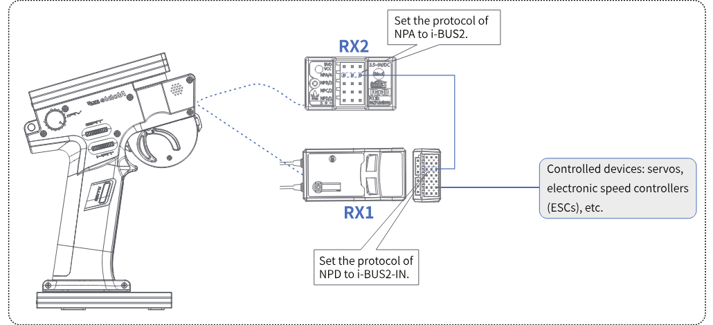
- Refer to the diagram to connect RX1 and RX2: Use a double-female header Dupont cable to connect RX1's NPD connector with RX2's NPA connector. Connect the controlled device to the connector of RX1.
- Bind RX1 and RX2 separately: Select RX SET > Bind Set, then select Two Rx mode, to complete the binding of RX2 (the master receiver) to the transmitter. Complete the binding of RX1 (the slave receiver) to the transmitter.
- Set the Newport connector protocols for RX1 and RX2: Select RX SET > Receiver Interface Protocol > Master Receiver > NPA, click on i-BUS2, and then click the back arrow to return. Select Slave Receiver > NPD, click on i-BUS2-IN and then click the back arrow to return.
- View the related information in the Sensor functionality: Enter the Sensor function interface and scroll up and down to view the related information. If the interface displays information such as "RX Voltage - RX1", it indicates that the setup is complete, and the signal redundancy feature can be activated.
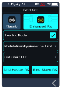
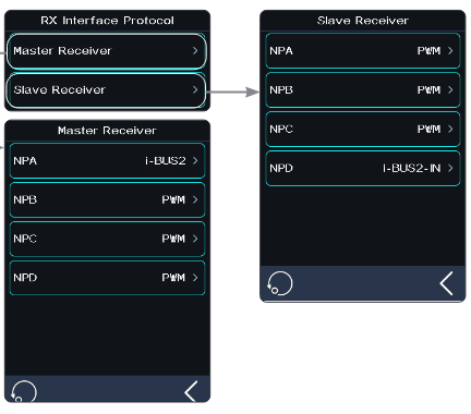
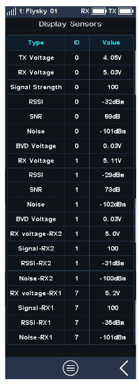
7.5Failsafe
Note: This function was updated in version 1.0.17.
The system provides the following settings for the failsafe function:
- To set the failsafe judgment time.
- Set to disable the signal output of i-BUS-out and PPM protocol connectors in case of out-of-control, i.e., no output at i-BUS-out & PPM connectors in case of losing control.
- Configure failsafe settings per channel: Each channel can be individually set to one of four modes: [Not Set (No Output)], [Channel Value None Output], [Fixed Value], or [Hold].
- [Set all fixed value channels], namely, you can set the output value of all channels that have been set to a fixed value, and this value will be output when the system is losing control.
- The failsafe function can be tested. The model can simulate an out-of-control, after which the transmitter will shut down RF output, and the model will enter a failsafe state, with all channels outputting according to the failsafe settings.
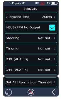
Failsafe Test Function
Used to simulate the out-of-control case: when the model is out-of-control, the transmitter will shut down the RF, then the model will enter the out-of-control state. All channels will output according to the failsafe settings.
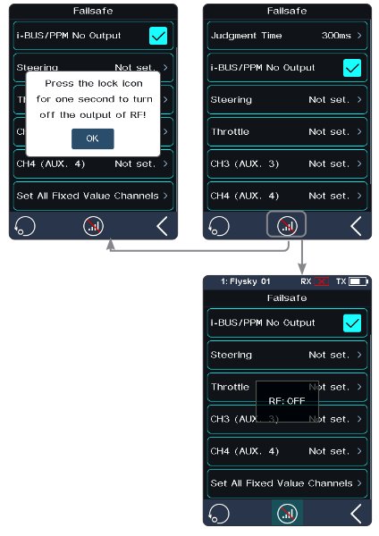
Setup:
- Tap the test icon; a popup window comes along with it as shown. Press and hold the icon for over 1 second, then the system turns off the RF, and the receiver outputs the channel values according to the failsafe settings.
- Release the icon; the RF is on and the connection is restored.
Failsafe Judgment Time
Used to set the failsafe judgment time; the setting range is from 250ms to 1000ms. By default, it is 300ms.
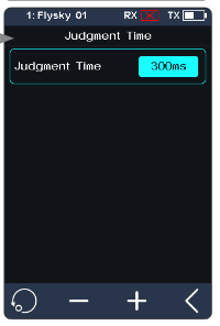
Setup:
- Tap [Judgment Time] to enter the setting interface.
- Click +/- to set the appropriate value, then click the back arrow to return.
i-BUS & PPM No Output
This function is for i-BUS and PPM signals. After [i-BUS/PPM No Output] is enabled, regardless of the setting of the failsafe, these two types of failsafe signals are always no output. If the function is disabled, after losing control, you can set by channel: set to a fixed value or keep the last output value. By default, this function is enabled.
Tap the check box at the right side of [i-BUS/PPM No Output]; if it is not ticked, it indicates that the function is disabled.
Setting a Separate Channel
Used to set the output signal states of channels respectively: [Not set (No output)] means the failsafe of this channel has not been set, and there is no output in case of out-of-control. [Channel Value None Output] means that there is no output in case of out-of-control; [Hold] means the last channel value is kept in case of out-of-control; [Fixed Value] means that you can set the failsafe output value by moving the control, then the value set will output in case of out-of-control.
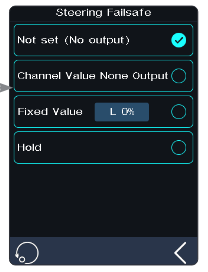
Setup:
- Tap the channel you want to set.
- Click an appropriate option as desired. If the fixed value is selected, move the throttle trigger (steering wheel, button or knob) to the desired position and hold it, then click the back arrow to finish the settings.
Note: If the failsafe function of all channels is not set (no output), and the [Failsafe warning] function of [SYSTEM] is turned on, a pop-up window will appear after the transmitter is turned on to remind you that the failsafe function is not set.
Setting All Fixed Value Channels
Used to set the output value of all channels that have been set to a fixed value after out-of-control.
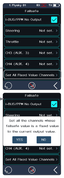
Setup: Tap this function while moving the control to the desired position and holding; after that a prompt interface comes along with it as shown. Click "YES" to finish.
Note: Gas-powered models are slightly different from battery-powered models when it comes to failsafe setup.
- Gas-powered: It is recommended to set the failsafe setting as if in the vehicle's brake state, that is, set the throttle channel output value of the vehicle when subjected to brake as the failsafe value. The braking effect can be customized accordingly.
- Battery-powered: 1. It is recommended that the failsafe is set to Free. In case of out-of-control, it will enter the braking state when the ESC does not receive signals. 2. It is also possible to set the failsafe setting as if in the vehicle's brake state, same as gas-powered.
- Some ESCs also use braking as reverse; make sure to check this with your model.
7.6Servos Frequency
This function is used to select the frequency of channel data PWM signals. The function includes analog servo (95 Hz), digital servo (380 Hz), and custom. You can select or set the correct output frequency value according to the servo used. By default, the system adopts the digital servo. The custom frequency adjustment range is 50-400 Hz.
The servos frequency varies slightly with the connected receivers.
For the Classic Edition Receiver
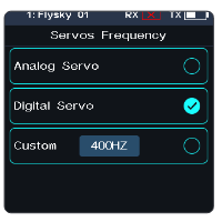
- Click [Servos Frequency].
- Click the corresponding option. Click the back arrow to return to the previous level interface. If the transmitter RF Setting is set to [AFHDS 3 1 way], modify the servo response speed and then tap the back arrow. The system prompts "It takes effect after bind or re-bind. Are you sure you want to bind?"
- If you choose [Custom], click "+" or "-" to adjust the frequency.
For the Enhanced Edition Receiver
- [SR]: One of the specifications in the servo frequency (PWM frequency is 833 Hz).
- [SFR]: One of the specifications in the servo frequency (PWM frequency is 1000 Hz).
Note: When SR (PWM frequency: 833 Hz) and SFR (PWM frequency: 1000 Hz) are selected, the overall system delay will be decreased, but the pulse range of PWM signals is changed. Please make sure the servo supporting the corresponding frequency is a digital servo and the setting is correct. Otherwise the servo may not work properly, or even get damaged.
Setting a Channel
Sets the PWM frequency for a channel.
[Synchronized with RF]: The PWM output is synchronized with the timing of the (RF) radio signal reception.
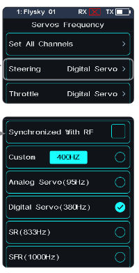
Setup:
- Click [Steering Digital Servo] or other options to enter the function setting interface.
- Click the corresponding servo frequency according to the actual state of the adapted receiver. Click the back arrow to return to the previous level interface. If you have checked [Synchronized with RF], the icon will change to checked. The PWM output is synchronized with the timing of the (RF) radio signal reception after it is checked.
- If you choose [Custom], click "+" or "-" to adjust the frequency value.
Setting All Channels
Sets the PWM frequency for all channels. For function setup, refer to the setup section of Setting a Channel above.
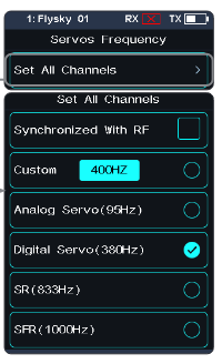
7.7i-BUS2 Setup
This function is used to set up the i-BUS2 devices. For details, see 6.25 i-BUS2.
7.8i-BUS Setup
This function is used to set up the i-BUS expansion module.
The i-BUS function is mainly used for servo expansion. If a cable is too short or the number of servos exceeds the outputs of the receiver, the i-BUS serial bus receiver provides a convenient option for expansion. When using the i-BUS serial bus receiver, make sure that it is powered separately to ensure that the servos have sufficient power.
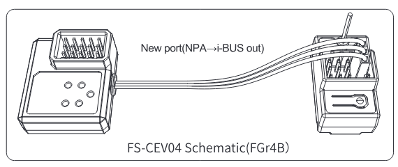
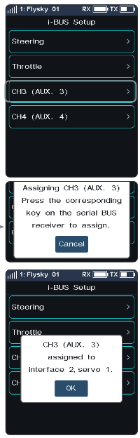
Setup:
- Turn on the transmitter and enter [MODEL], then tap [Channel Number Definition], and select the number of channels to be set (optional 2, 4, 6, 8, 10, 12, 18 channels; the system defaults to 8 channels).
- Go to [RX SET] and bind the transmitter and receiver.
- Tap [RX Interface Protocol] and select [i-BUS out].
- Connect the FS-CEV04 to the FGr8B/FGr4B receiver's [i-BUS out] interface.
- Touch [i-BUS Setup] and select the channel to be assigned (touch "channel X"; the system displays "Assigning channel X. Press the corresponding key on the serial BUS receiver to assign"). Use the appropriate tool to press the K1, K2, K3 or K4 button on the FS-CEV04 to assign the selected channel to C1, C2, C3 or C4. If successful, the transmitter will display: "Channel assigned to interface X / Servo X".
- Connect the servo to the corresponding port and check if it is working as expected.
- Repeat the above steps as needed.
7.9Config PWM Converter
This function allows you to configure the corresponding receiver as a PWM converter. After the setting is successful, the receiver is used as a PWM converter, and the interfaces output PWM signals.
Note: This function is not available for all receivers. For the classic receivers, only the FGr4 and FTr10 receivers are available.
- The receiver which is set as the PWM converter can be converted back into a receiver by rebinding the transmitter, and then used normally as a receiver after successfully rebinding the transmitter.
- [i-BUS To PWM]: This feature is adapted to classic edition or enhanced edition receivers to configure as a PWM converter. For the classic edition receivers, after it is set as a PWM converter, its SENS interface is connected to the interface of the receiver outputting i-BUS or i-BUS out. For the enhanced edition receivers, after it is set as a PWM converter, its NPA interface is connected.
- [i-BUS2 To PWM]: This feature is adapted to enhanced edition receivers to configure as a PWM converter. After it is set as a PWM converter, its NPA interface is connected to the interface of the receiver outputting i-BUS2. And you can set related parameters through [i-BUS2]; refer to 6.25 i-BUS2.
i-BUS To PWM
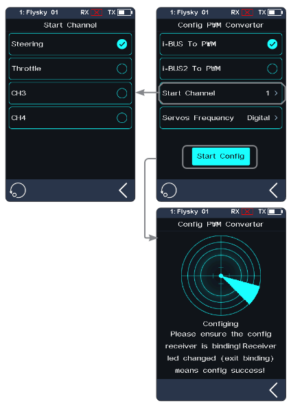
Setup:
- Enter the interface of Config PWM Converter and tap [i-BUS To PWM].
- Tap [Start Channel] to enter the setting interface, then set the start channel for the PWM converter. For example, if the receiver has 4 channels, and since one of the channels is used as an extension interface, then the start channel of the PWM converter can be set to "4".
- Tap [Servos Frequency Digital] to enter the setting interface to set the servo frequency for the PWM converter. Then click [Start Config]; the configuring interface comes along.
- Put the receiver into the binding state; after the status of the receiver LED changes from fast flash to two-flash-one-off, it indicates the configuration is finished. Then click the back arrow to return.
If you set the receiver as an i-BUS2 PWM converter, there is no need to set [Start Channel] and [Servos Frequency].
7.10RSSI Output Setup
Through this function, you can select a channel to output the signal strength value of the receiver. After the function is enabled, the selected channel does not perform the output of the transmitter's corresponding channel function, but outputs the receiver's signal strength value. This feature is necessary for FPV players with autopilot. We recommend you to select CH14 or any auxiliary channel. You can make corresponding adaptations in the settings to view the RSSI information on FPV glasses.
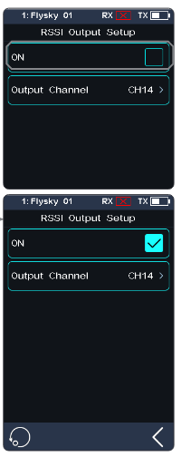
Setup:
- Tap the check box on the right side of [ON] to enable this function.
- Click [Output Channel] to enter, and tap the corresponding channel. Click the back arrow to return to the previous level interface.
7.11RX Battery Monitor
This function is used to detect the voltage status of the receiver or the corresponding sensor battery.
Set the high and low battery voltages according to the actual usage of the receiver battery and the remaining battery level displayed through the icon in the upper right corner of the interface. The transmitter will promptly send an alarm according to battery conditions.
When the receiver or sensor battery voltage is lower than the [Alarm voltage] alarm value, the transmitter will report "The receiver voltage is low" and give a vibration prompt; refer to 8.6 Sound and 8.7 Vibration of [System] for turning on/off the sound/vibration, as well as setting an appropriate level.
[Sensor]: The voltage of the voltage sensor is used as the voltage of the receiver. [Internal Voltage], [External Voltage], [BVD Voltage], [ESC Power] or [Sensor Power] can be selected. After selection, it can be displayed and alarmed through the transmitter.
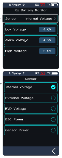
Setup:
- Tap [Rx Battery Monitor] to enter the setting interface.
- Click [Sensor] to enter and select an internal or external sensor.
- When the Sensor is set as the voltage sensor, then set the [Low Voltage], [Alarm Voltage], and [High Voltage] values; when the Sensor is set as [ESC Power] or [Sensor Power], [Alarm Power] and [Full Power] can be set. [Low Voltage] corresponds to a receiver battery level of 0%; [High Voltage] corresponds to a receiver battery level of 100%. [Alarm Power] corresponds to the power in case of the alarm; [Full Power] corresponds to an ESC/sensor battery capacity of 100%.
Notes:
- [ESC Power] is only applicable for Hobbywing XERUN AXE R2/R3 ESCs.
- When multiple XERUN AXE R2/R3 ESCs are connected, the setting is for the first ESC connected.
- [Internal Voltage] corresponds to the voltage of the receiver; [External Voltage] corresponds to the voltage detected by the FS-CVT01 sensor; [BVD Voltage] corresponds to the voltage detected through the BVD function; [ESC Power] corresponds to the power of the XERUN AXE R2/R3 ESC; [Sensor Power] corresponds to the power of the Current and Voltage Sensor.
7.12Range Test
This function is used to test whether wireless communication between the transmitter and the receiver is normal.
As the actual remote control distance between transmitter and receiver is far, it is hard to test whether the radio frequency is normal by controlling at a distance of several hundred meters between the transmitter and receiver in practice. Theoretically, the remote control distance in this function will be reduced to 30-40 meters. So, you can test whether wireless communication between the transmitter and the receiver is normal at a close distance when the function is enabled. This can save testing time.
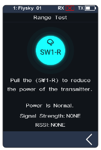
Setup:
- Make sure the transmitter and receiver are bound.
- Enter the [Range Test] menu and press the SW1-R button.
- One person stands in place with the model in hand, and the other person holds the transmitter and gradually moves away to 30-40 meters and walks around with this distance as a radius centered on this model. Please make sure the transmitter is installed with the phone holder, with use of the standard version firmware. Make sure that the transmitter antenna is unobstructed and that there are no objects or sources of interference between the transmitter and the receiver.
- Check the RSSI on the transmitter. If the signal strength is high and stable, it means that the radio frequency of this system works normally.
7.13BVD Voltage Calibration
There may be a voltage difference between the voltage detected by the receiver and the actual voltage of the battery. Use this function to set a calibration coefficient for the receiver to make the voltage displayed on the interface equal to the battery voltage, namely, the sum of the detection voltage and the calibration coefficient is equal to the voltage displayed on the interface.
The BVD voltage detection range is from 0 to 70V.
Battery Voltage: Displays the battery voltage detection value returned by the receiver in real time. This feature is only subject to the enhanced edition receiver.
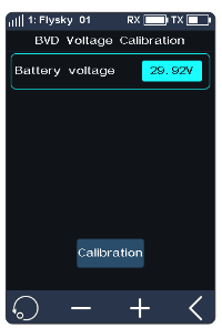
Setup: Connect the BVD detection line correctly before setting, and then perform calibration. Note: please refer to the voltage value of a multimeter for calibration.
- Click [BVD Voltage Calibration] to enter the function setting interface.
- Click "+" or "-" to change the battery voltage value as needed.
- Click [Calibration]. After successful calibration, click "YES" in the pop-up window reminder.
Notes:
- This function is available for enhanced edition receivers with BVD function, which must be in two-way communication with the transmitter.
- In two receivers' mode, this function is only applicable to the master receiver. In such case, first calibrate the BVD voltage of this receiver and then use it as a Slave receiver to bind with the transmitter.
- Pay attention to correctly connecting the BVD cable and the anode and cathode of the battery as shown in the diagram.
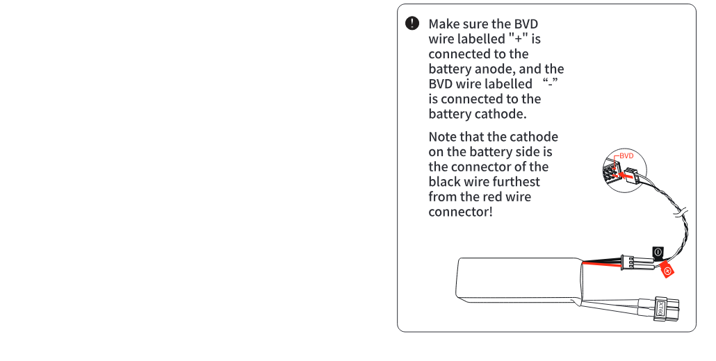
7.14Low Signal Alarm
Note: This feature is only applicable to version 1.0.12 and later.
This feature is used to configure the alarm function for signal strength when the transmitter and receiver communicate in two-way mode.
You can set a specific alarm threshold for signal strength, enable or disable repeated alarms, and adjust the time interval for repeated alarms. Additionally, you can select the type of alarm sound.
Once the low signal alarm function is enabled, the transmitter will trigger a low signal alarm according to the configured settings when the receiver's signal strength falls below the set threshold.
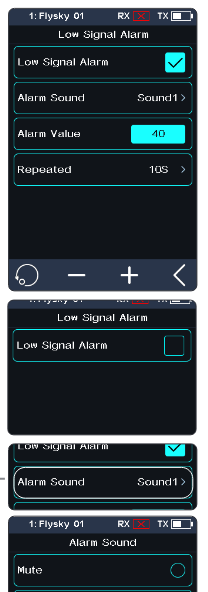
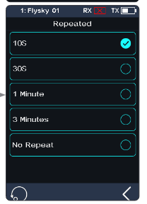
Setup:
- Tap [Low Signal Alarm] to enter the settings interface.
- Tap the function box to the right of [Low Signal Alarm]: if it is unchecked, the feature is disabled; if it is checked, the feature is enabled.
- Tap [Alarm Sound] to proceed to the next level interface. After selecting the appropriate alarm sound, click the back arrow to return.
- Set the [Alarm Value]: Click "+" or "-" to set the appropriate signal strength threshold for the alarm.
- Tap [Repeat] to proceed to the next level interface. After selecting the appropriate function item, click the back arrow to return.
Notes:
- If double receivers are bound, when both primary and secondary receivers are connected, the alarm will activate when the primary receiver's signal strength drops below the set value; if only the secondary receiver is connected, the alarm will activate when the secondary receiver's signal strength is below the set value.
- If the alarm sound (SYSTEM > Sound > Alarm Sound) is turned off, the alarm sound configured here will not trigger any notifications.
7.15Telemetry Loss Alarm
Note: This feature is only applicable to version 1.0.12 and later; it was updated in version 1.0.22.
Used to set the alarm function when the transmitter does not receive the information returned by the receiver. You can configure whether to enable the signal loss alarm, the alarm sound, and the trigger time for the alarm (Sensitivity).
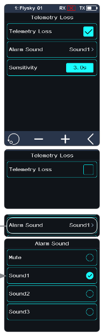
Setup:
- Tap [Telemetry Loss] to enter the settings interface.
- Tap the function box to the right of [Telemetry Loss]: if it is unchecked, the feature is disabled; if it is checked, the feature is enabled.
- Tap [Alarm Sound] to enter the next level interface, and tap the appropriate type. Then click the back arrow to return.
- Tap [Sensitivity], then click "+" or "-" to adjust the trigger value.
Notes:
- If double receivers are bound, the system will only activate the alarm when both the primary and secondary receivers lose their signal connection, i.e., when they both disconnect.
- If the alarm sound (SYSTEM > Sound > Alarm Sound) is turned off, the alarm sound configured here will not trigger any notifications.
- When the channel quantity is set to [2 Channel (Fast)] in the [Channel Number Definition], this alarm is disabled by default.
7.16Update Receiver Firmware
After each transmitter update the receiver firmware will need to be updated.
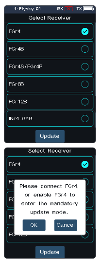
Setup: Touch [Update Receiver].
- Some receivers such as the GMr need to be updated with "Flysky Assistant".
If the transmitter has successfully bound and the connection is established: if the receiver firmware is the latest version, a pop-up prompt will appear [The current version is the new version, no upgrade is required!]. If the receiver firmware is an old version, a pop-up prompt [Are you sure to update the receiver?] appears. Click [Yes] to update the receiver firmware.
If the receiver and the transmitter are not connected, then enter the receiver selection interface (FGr8B/FGr4B need to be placed upright when in use), check the receiver to be connected and a prompt pops up [Please connect XX or enable XX to enter the mandatory update mode]. Click [OK]!
After entering the update, when the progress is 100%, the update is successful.
Note: You must update the transmitter firmware before updating the receiver firmware.
The steps of the forced update of the receiver firmware are as follows:
- Power on the receiver while pressing the BIND button for more than 10 seconds, until the LED is in a state of three-time flashing and one off, then release the BIND button. Or power on the receiver first, then press and hold the BIND button for more than 10 seconds; the LED of the receiver will be in a state of three-time flashing and one off, then release the BIND button.
- Power on the transmitter and select [Update Receiver]. Click the corresponding receiver. Select "OK" on the pop-up box. Click [Update] to enter the update state.
- When the update has finished, the receiver LED flashes slowly.
- This procedure applies to the FGr4B receiver; different receivers may enter the forced update in different ways. Please go to the FLYSKY website to query the instructions of the relevant receiver.
7.17Steering ICS
This function is used to set the parameters of the gyroscope mixing steering channel of the vehicle control base board.
This function can be set when the transmitter RF Standard is set to [Mini-Z(EVO2)]. It will be hidden when the RF is set to other standards.
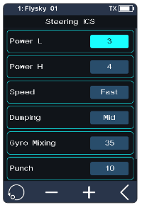
Setup:
- Tap the function item you want to set.
- Click "+" or "-" to change the option or value.
7.18Throttle ICS
This function is used to set the parameters of the gyroscope mixing throttle channel of the vehicle control base board.
This function can be set when the transmitter RF Standard is set to [Mini-Z(EVO2)]. It will be hidden when the RF is set to other standards.
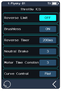
Setup:
- Tap the function item you want to set. For the functions [Reverse Limit] and [Brushless], tap repeatedly to select between OFF and ON.
- Click "+" or "-" to change the option or value for other functions.
8SYSTEM
This section introduces details of the functions related to the system and their use.
8.1USB Setup
USB Setup is used to support the output signals of the Type-C port.
- [USB Function]: When the input or output is a USB signal, you can control the simulator and connect the computer and FlySky Assistant.
- [Trainer Mode]: When the input or output is a PPM signal, it can realize the trainer and head tracker functions.
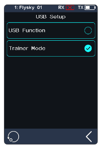
Setup:
- Click [USB Setup] to enter the selection interface. Select USB Function; the trainer function is not displayed (it is displayed in case of selecting the trainer function).
- Click the back arrow to return and save.
8.2Theme
It is used to set the overall color style of the system, with 4 options.
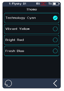
Setup:
- Touch [Theme] to enter the menu.
- Select a theme as desired.
- Touch the back arrow to return to the previous menu and save the setting.
8.3Wallpaper
It is used to set the wallpaper of the home screen and main menu.
- [Home Screen Wallpaper]: Sets the wallpaper of the home screen.
- [Main Menu Wallpaper]: Sets the wallpaper of the main menu.
Wallpaper preview: To preview the wallpaper in full screen and hide the options, click the area outside the corresponding function option. Click again to exit the preview.
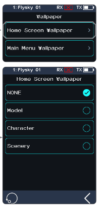
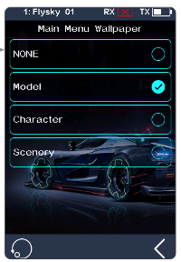
Setup: Please refer to 8.2 Theme.
8.4Units
Choose what units to use for length and temperature.
- [Length]: Select between the metric and imperial system. The default is Metric.
- [Temperature]: It can be selected in Celsius and Fahrenheit. The default is Celsius.
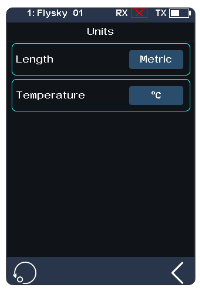
Setup: Please refer to 8.2 Theme.
8.5Backlight Adjustment
This function controls the backlight brightness.
Note: Turning the brightness up will use more power; the longer the backlight timeout, the more power consumption, the shorter the battery using time.
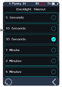
- [Backlight Timeout]: Select the delay time. That is, when there is no action, the screen is reduced to the minimum brightness state after the corresponding backlight delay time. Tap [Backlight Timeout] to enter, and select an appropriate item as needed. Then click the back arrow to return and save.
- [Max Backlight]: The backlight state of the transmitter display when the backlight is strongest. The adjustment range is 10%-100%. Tap [Max Backlight] to enter, and click "+" or "-" to change the percentage as required.
- [Mini Backlight]: The backlight state of the transmitter display when the backlight is weakest. The adjustment range is 0%-50% (the screen is not bright at 0%). The adjustment method is the same as above.
8.6Sound
This function is used to turn on or off the sound of different functions and to adjust the volume.
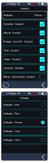
- [Volume]: To set the volume. Tap [Volume], then select the desired volume from the list. Touch the back arrow to return to the previous menu and save it.
- [System Sound]: To turn on or off the system sound. Click the option box on the right side of the interface. The icon will change to checked, indicating that the system sound is enabled.
- [Alarm Sound]: To turn on or off the alarm sound.
- [Power On/Off Sound]: To turn on or off the power-on/off sound. Click the option box on the right side of the interface to enable. After it is enabled, the system will sound "Welcome to Noble Plus" when turned on, and the system will sound "Shutting down" when turned off.
- [Trim Sound]: To turn on or off the trim sound.
- [Timer Sound]: To turn on or off timer related prompt sounds.
- [Sensor Sound]: To turn on or off sensor alarm related prompt sounds.
- [Menu Operation Sound]: To turn on or off the prompt sound when a touch screen operation takes effect.
Note: For details about how to set other functions, refer to the system sound settings.
8.7Vibration
This function is used to enable or disable the vibration of different functions.
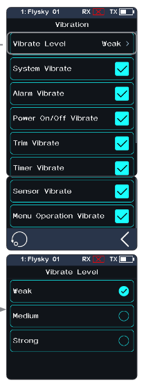
- [Vibrate Level]: To set the intensity of the vibration level. Tap [Vibrate Level], then select the desired level from the list. Touch the back arrow to save.
- [System Vibrate]: To turn on or off the system vibration. Tap the box at the right of "System Vibrate". If there is a check in the box, the function is enabled.
- [Alarm Vibrate]: To turn on or off the alarm vibration.
- [Power on/off Vibrate]: To turn on or off the power on/off vibration.
- [Trim Vibrate]: To turn on or off the trim operation prompt vibration.
- [Timer Vibrate]: To turn on or off timer related prompt vibrations.
- [Sensor Vibrate]: To turn on or off sensor alarm related prompt vibrations.
- [Menu Operation Vibrate]: To turn on or off the prompt vibration when a touch screen operation takes effect.
Note: For details about how to set other functions, refer to the system vibration settings.
8.8LED
The LED function can change the color of the LED strip which is located above the power button of the transmitter, as well as the brightness of the LED strip. And it can also be set as the power capacity indication.
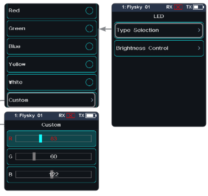
Type Selection
Allows you to turn the LEDs on/off, as well as to customize the LED color or select a color already defined in the options.
Setup:
- You can choose to turn off the LED.
- The LED can be used for power capacity indication (displaying different colors according to the current battery voltage): High – green, Medium – yellow, Low – red.
- Select a color from the list.
- To customize LED colors: Tap the R, G or B option area, and then tap "+" or "-" to set the appropriate value; you can also touch and slide the screen directly to set it. Tap the back arrow, and then tap [Yes] in the pop-up window to finish the setting.
Brightness Control
To set the LED brightness. Touch "+" or "-" to adjust the LED brightness. After setting, tap the back arrow to save and exit.
8.9Low Power Mode
Note: This function is available for version 1.0.9 or later.
This function is used to reduce the power consumption of the transmitter to extend the duration of the battery.
Low Power Mode will only take effect under the following conditions: when no receiver is connected, or when a receiver is connected and the RF standard is set to AFHDS3 1 Way, Mini-Z (EVO), or Mini-Z (EVO2). Once entering low power mode, the transmitter will enter a screen-off state and the transmission power will be reduced. Please note that when the radio control distance is approximately 10 meters, signal loss may occur. Due to interference in different environments, the actual signal loss distance may vary.
To exit low power mode, you can operate the transmitter controls or tap on the transmitter display. After exiting low-power mode, the transmission power will return to normal. This feature is disabled by default.
[Effective Delay]: To set the time after which the low power consumption mode takes effect.
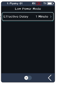
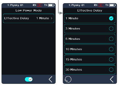
Setup:
- Enter the function interface, click [Effective Delay] to access the setting interface.
- Tap an appropriate option as needed, then click the back arrow to return.
- Tap the on/off icon to enable the function.
8.10Failsafe Warning
Note: This function was updated in version 1.0.17.
To check or uncheck the [Failsafe Warning].
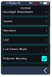
Setup: Tap the box to the right of the function. If there is a check in the box, the function is enabled.
Note: When [Failsafe Warning] is enabled, and the failsafe for all channels is in [Not set (No output)] status, a pop-up window will prompt that the failsafe has not been set after the transmitter is turned on.
8.11Quick Access
This function is used to set up the Up, Down, Left and Right quick sliding screen functions of the main interface. Users can customize the sliding screen interface according to their needs.
The [Quick Access] can help users find setting interfaces quickly. For example, when users want to check the lap counting time after the function is enabled in the model operations, users can use this function to enter the timer interface quickly.
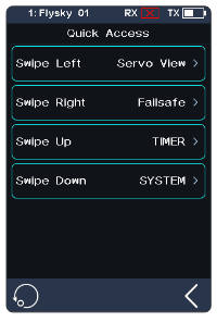
Setup:
- Enter the function interface, click the corresponding function option to choose it.
- Tap an appropriate option as needed.
- Click the back arrow to save the settings.
Note: When sliding the screen, it is recommended to slide as close to the edge of the home screen as possible.
8.12Main Screen Lock Setup
This function is used to set the state of the transmitter after the main interface is locked.
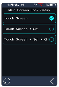
- [Touch Screen]: It can prevent the transmitter screen from being touched by mistake, because this may change the parameters that have been set.
- [Touch Screen + Set]: Only channels are controllable after selection. This can avoid changing the set parameters when someone else performs operations or accidentally toggles a switch.
- [Touch Screen + Set + CH]: After locking, all knobs, keys, or trims are unavailable. This can prevent others from modifying channel data when operating on behalf of others or changing setting parameters by accidentally toggling a switch.
You can click the corresponding function according to your needs. If it becomes checked, the function is enabled.
8.13Standby Timeout
This function is used to set standby timeout intervals or no standby timeout alarm. 5 options: [NONE], [3 Minutes], [5 Minutes], [10 Minutes] and [20 Minutes]. [NONE] means no standby timeout alarm. The time to alarm can be selected as desired. The default is 3 minutes.
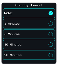
Click [Standby Timeout] to enter the setting menu, and click the option as required. For example, if you set the alarm time to 3 minutes, the system will give a vibration and audio alarm when the transmitter is idle for 3 minutes. You can set the on/off and volume of the sound, and the on/off and level of the vibration in 8.6 Sound and 8.7 Vibration of [System].
8.14Auto Power Off
Note: This function was updated in version 1.0.17.
Long-term operation may affect battery life. You can enable or disable the Auto Power Off function and set the auto power off timer.
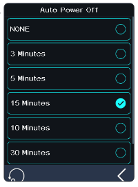
Setup:
- Tap Auto Power Off to enter the setting interface.
- Tap an appropriate option as needed, then touch the back arrow to save and return to the previous menu.
8.15Stick Calibration
Note: This function was updated in version 1.0.17.
Use this function to correct the mechanical deviation of the throttle trigger and steering wheel, for example, deviation occurring in the self-centering or maximum/minimum travel.
The function interface will display the current calibrated channel value and the previous calibrated value.
The blue bar is the channel's current position and the calibrated range will be the same color as the background.
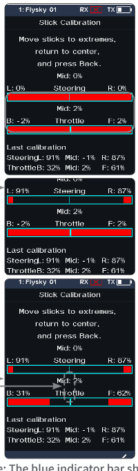
Setup:
- Move the steering wheel and throttle trigger as far as they can go in each direction. Then release them to make them return to the neutral position.
- Touch the back arrow to save and return to the previous menu.
Note: The blue indicator bar shows only the mechanical midpoint position of the steering wheel or throttle trigger. The "Mid" value reflects the real-time midpoint reading. As different triggers and wheels have varying movement ranges, the calibration display may adjust accordingly. After successful calibration, verify the channel outputs in the [Servo View] interface.
8.16Firmware Update
In case of updating the firmware of the transmitter, use this function to put the transmitter into updating mode first, then upgrade the transmitter's firmware.
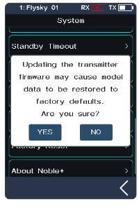
Setup:
- Download and open the newest official software.
- Connect the transmitter with a computer by USB Type-C cable.
- Touch [Firmware Update], after which "Updating the transmitter firmware may cause model data to be restored to factory default values. Are you sure?" will be displayed. Touch "YES" to enter update mode.
- After completing the above steps, click [Update] in the software on your computer to start the update.
- The transmitter will power on again when the updating process is completed. Then remove the USB Type-C cable and close the firmware.
Note: The model data will be reset after the firmware update. Back up the model data before you perform the firmware update.
- Use the USB Type-C cable shipped with the transmitter.
- Do not unplug the USB Type-C cable while the firmware is updating.
The firmware of the transmitter can also be updated by FlyskyAssistant. In such case, just make sure the transmitter is turned on and connected to the computer.
8.17Factory Reset
The Factory Reset function resets all of the transmitter settings and functions back to their factory default state/data.
Setup: Touch "Factory Reset", then touch "YES" when prompted.
Note: To avoid errors, do not use this function during operation.
8.18About Noble NB4+
This function contains basic information such as product name, firmware version, version date, hardware and RF library version.
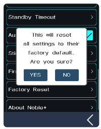
9Transmitter Specifications
This chapter includes specifications for the Noble NB4+ transmitter and FGr4B receiver.
9.1Transmitter Specifications (Noble NB4+)
| Product Model | Noble NB4+ |
| Compatible Receivers | FGr4B and other AFHDS 3 receivers |
| Compatible RC Models | Car or Boat |
| Number of Channels | 8 |
| RF | 2.4GHz ISM |
| Maximum Power | < 20 dBm (e.i.r.p.) (EU) |
| RF Protocol | AFHDS 3 |
| Low Voltage Alarm | Lower than 3.65V |
| Data Connector | USB Type-C |
| Charging Jack | USB Type-C |
| Antenna | Single built-in antenna |
| Display | 3.5-inch 320 × 480 full dot matrix color IPS touch screen |
| Resolution | 4096 |
| Input Power | 1S (4.35V) 4300mAh lithium polymer battery + 3500mAh 18650 battery |
| Distance | More than 300m (ground distance without interference) |
| Firmware Update | Supported |
| Temperature Range | -10°C ~ +60°C |
| Humidity Range | 20% ~ 95% |
| Color | Black |
| Dimensions | 131.41 × 115.95 × 190.56mm |
| Weight | 520g |
| Certifications | CE, FCC ID: 2A2UNNB4PLUS00, MIC, RCM, IC: 25584-NB4PLUS00 |
9.2Receiver Specifications (FGr4B)
| Product Model | FGr4B |
| Number of PWM Channels | 4 |
| RF | 2.4GHz ISM |
| RF Protocol | AFHDS 3 |
| Antenna | Single antenna |
| Operating Voltage | 3.5~9V/DC |
| Data Output | PWM/PPM/i-BUS2/S.BUS/i-BUS |
| Temperature Range | -10℃ ~ +60℃ |
| Humidity Range | 20% ~ 95% |
| Firmware Update | Supported |
| Dimensions | 17 × 29 × 16.6mm |
| Weight | 6.4g |
| Certifications | CE, FCC ID: N4ZFGR4B000 |
10Package Contents
The accessories included are different in different editions; please consult your dealer for details.
11Instructions
11.1Trigger Spring Replacement
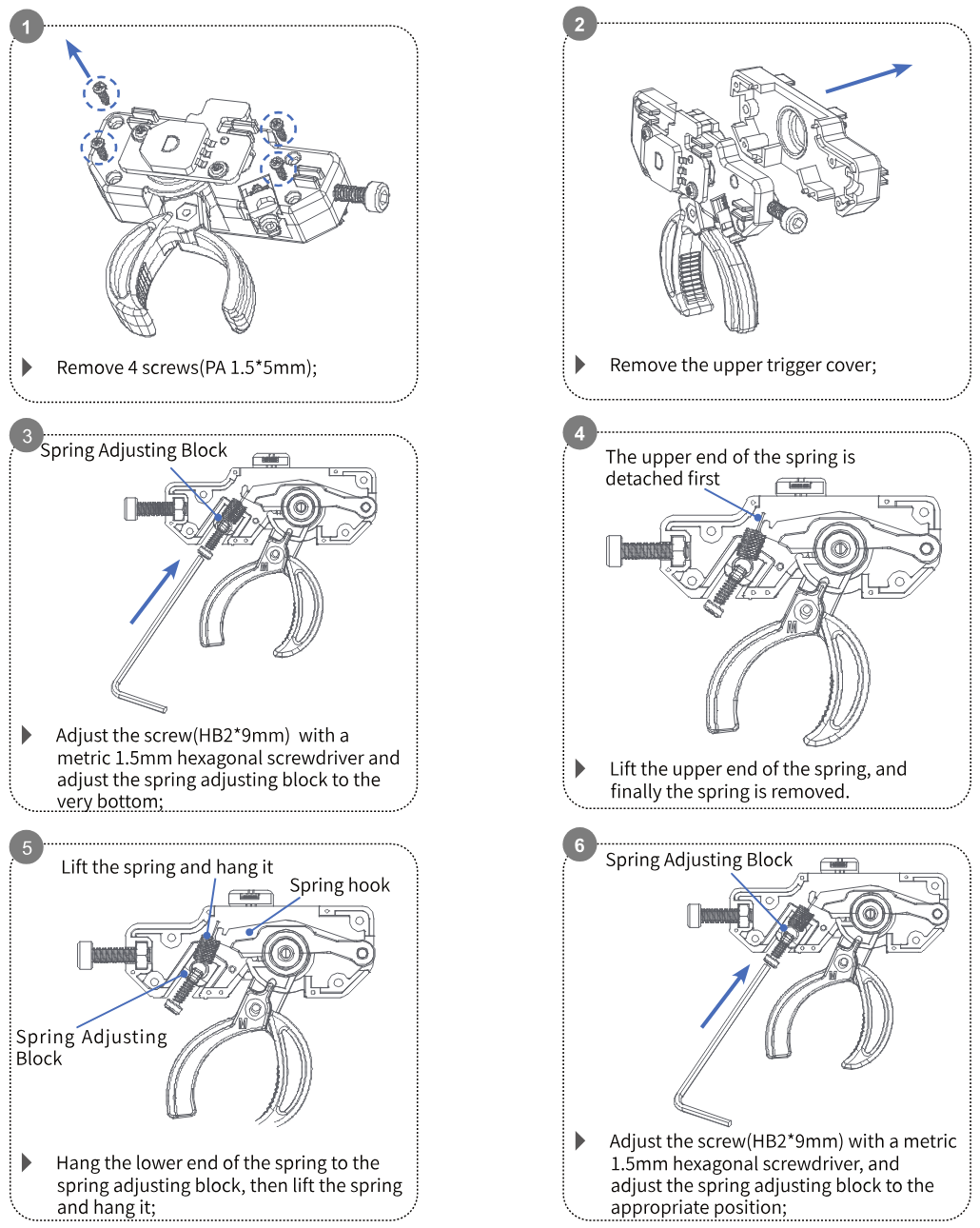
- Remove 4 screws (PA 1.5 × 5mm).
- Remove the upper trigger cover.
- Adjust the screw (HB2 × 9mm) with a metric 1.5mm hexagonal screwdriver and adjust the spring adjusting block to the very bottom.
- Lift the upper end of the spring; the upper end of the spring is detached first, and finally the spring is removed.
- Hang the lower end of the spring to the spring adjusting block, then lift the spring and hang it on the spring hook.
- Adjust the screw (HB2 × 9mm) with a metric 1.5mm hexagonal screwdriver, and adjust the spring adjusting block to the appropriate position.
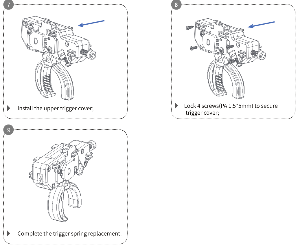
- Install the upper trigger cover.
- Lock 4 screws (PA 1.5 × 5mm) to secure the trigger cover.
- Complete the trigger spring replacement.
11.2Steering Wheel Spring Replacement
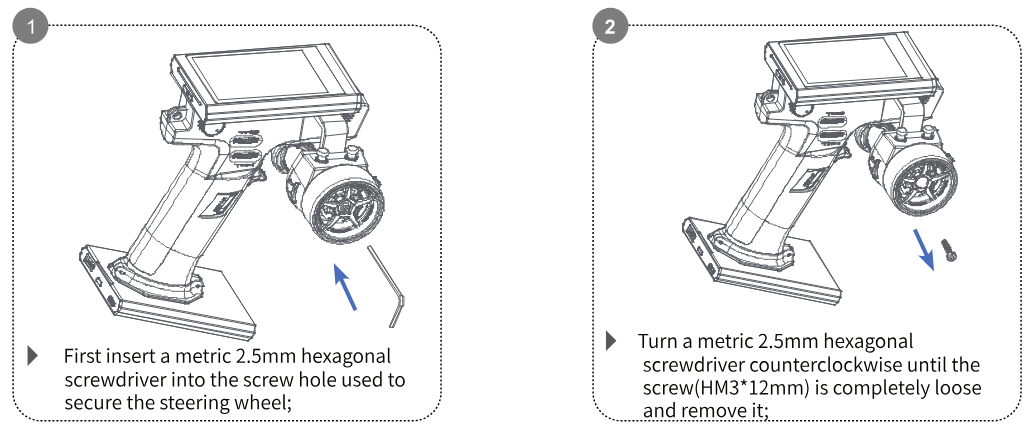
- First insert a metric 2.5mm hexagonal screwdriver into the screw hole used to secure the steering wheel.
- Turn the metric 2.5mm hexagonal screwdriver counterclockwise until the screw (HM3 × 12mm) is completely loose and remove it.
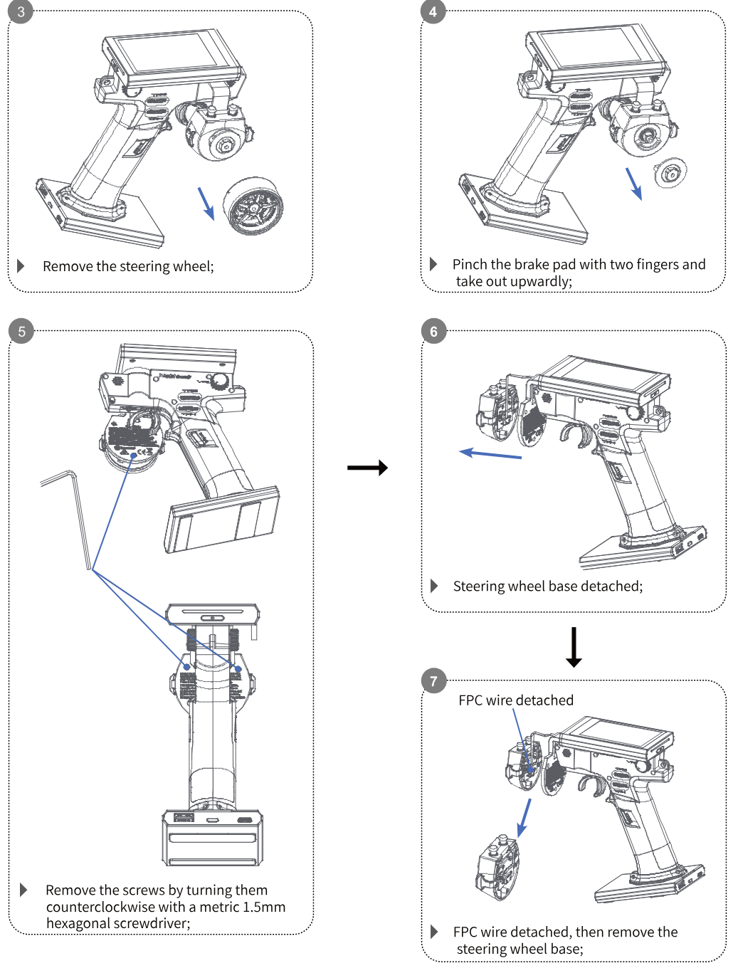
- Remove the steering wheel.
- Pinch the brake pad with two fingers and take it out upwards.
- Remove the screws by turning them counterclockwise with a metric 1.5mm hexagonal screwdriver.
- The steering wheel base is detached.
- Detach the FPC wire, then remove the steering wheel base.
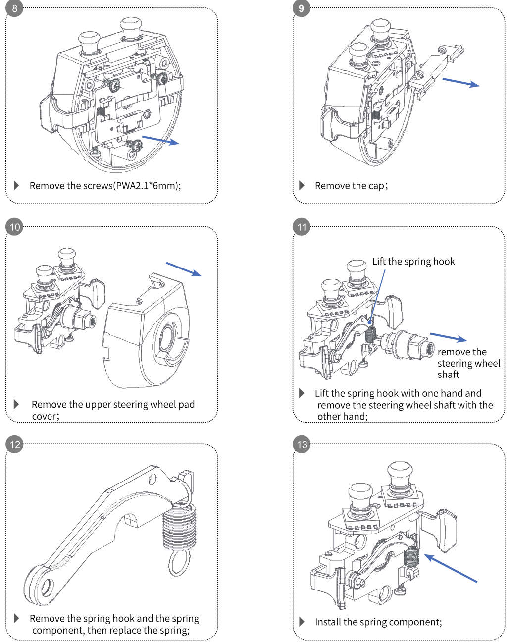
- Remove the screws (PWA2.1 × 6mm).
- Remove the cap.
- Remove the upper steering wheel pad cover.
- Lift the spring hook with one hand and remove the steering wheel shaft with the other hand.
- Remove the spring hook and the spring component, then replace the spring.
- Install the spring component.
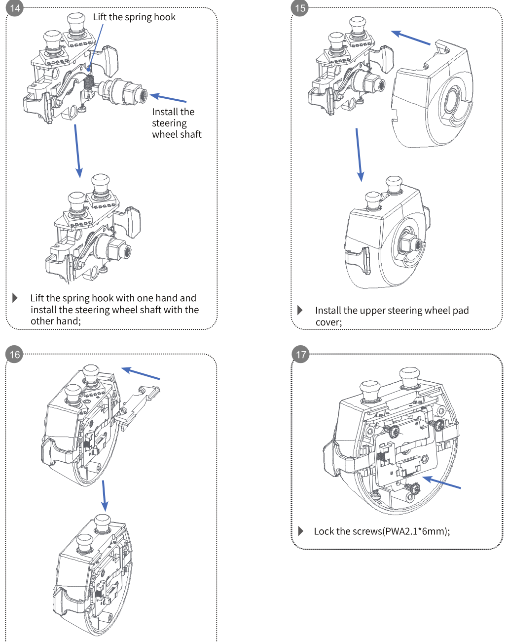
- Lift the spring hook with one hand and install the steering wheel shaft with the other hand.
- Install the upper steering wheel pad cover.
- Install the cap.
- Lock the screws (PWA2.1 × 6mm).
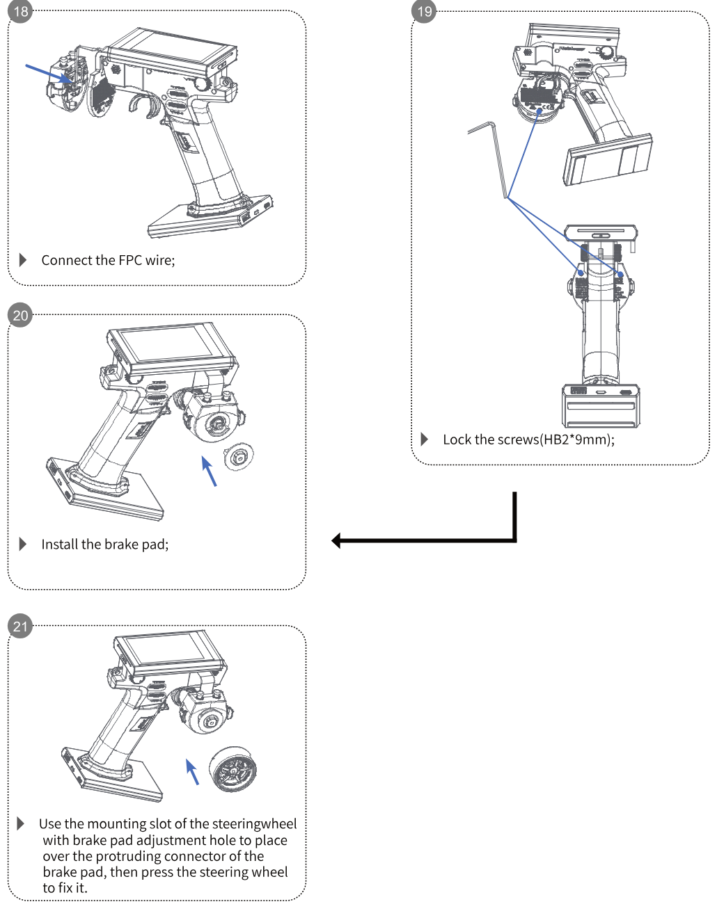
- Connect the FPC wire.
- Lock the screws (HB2 × 9mm).
- Install the brake pad.
- Use the mounting slot of the steering wheel with the brake pad adjustment hole to place it over the protruding connector of the brake pad, then press the steering wheel to fix it.
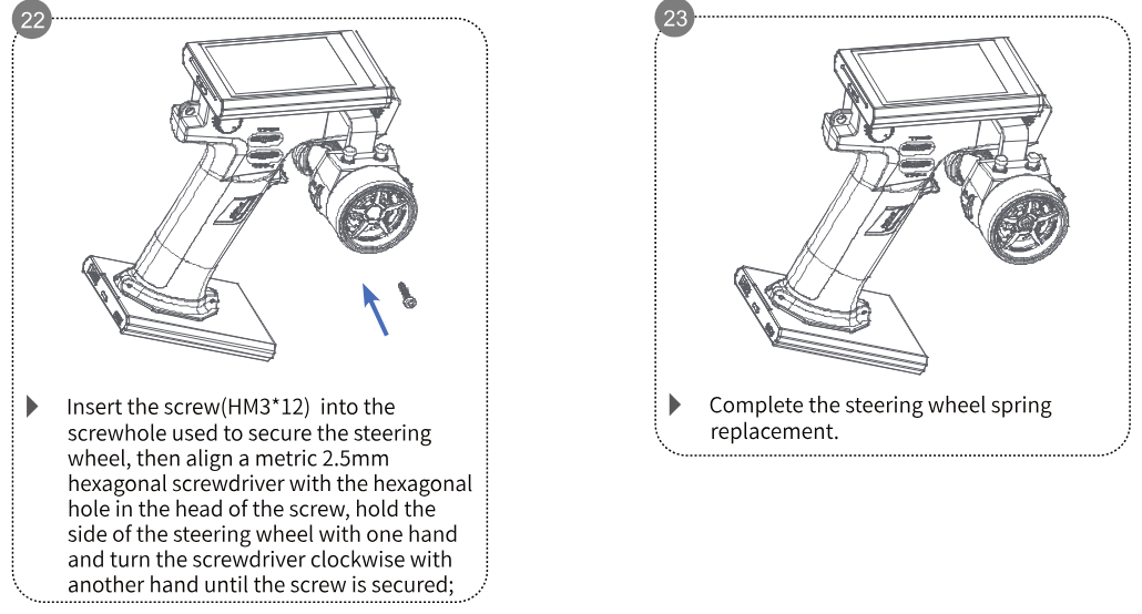
- Insert the screw (HM3 × 12) into the screw hole used to secure the steering wheel, then align a metric 2.5mm hexagonal screwdriver with the hexagonal hole in the head of the screw, hold the side of the steering wheel with one hand and turn the screwdriver clockwise with the other hand until the screw is secured.
- Complete the steering wheel spring replacement.
11.3Triggers Description
Three triggers are included in the package accessories for this transmitter.
- The opening size of the triggers marked S and L cannot be adjusted.
- The opening size of the other can be adjusted. The size of the opening must be adjusted by the screw on the side of the trigger.
It is recommended to replace the trigger with the appropriate one according to the actual situation.
12Certification
12.1DoC Declaration
Hereby, [ShenZhen FLYSKY Technology Co., Ltd.] declares that the Radio Equipment [Noble NB4+, NB4+] is in compliance with RED 2014/53/EU.
The full text of the EU DoC is available at the following internet address: www.flyskytech.com/info_detail/10.html
12.2CE Warning
The CE warns that the installation of the antenna used in this transmitter must be kept in distance from all the personnel and shall not be used or used with any other transmitter. The end user and the installer must provide antenna installation instructions and transmitter operating conditions to meet the requirements for RF exposure compliance.
12.3Environmentally Friendly Disposal
Old electrical appliances must not be disposed of together with the residual waste, but have to be disposed of separately. The disposal at the communal collecting point via private persons is for free. The owner of old appliances is responsible to bring the appliances to these collecting points or to similar collection points. With this little personal effort, you contribute to recycle valuable raw materials and the treatment of toxic substances.
- RISK OF EXPLOSION IF BATTERY IS REPLACED BY AN INCORRECT TYPE. DISPOSE OF USED BATTERIES ACCORDING TO THE INSTRUCTIONS.
- Replacement of a battery with an incorrect type can defeat a safeguard (for example, in the case of some lithium battery types).
- Disposal of a battery into fire or a hot oven, or mechanically crushing or cutting of a battery, can result in an explosion.
- Leaving a battery in an extremely high temperature surrounding environment can result in an explosion or the leakage of flammable liquid or gas.
- A battery subjected to extremely low air pressure may result in an explosion or the leakage of flammable liquid or gas.
12.4FCC Statement
This equipment has been tested and found to comply with the limits for a Class B digital device pursuant to part 15 of the FCC rules. These limits are designed to provide reasonable protection against harmful interference in a residential installation. This equipment generates, uses and can radiate radio frequency energy and, if not installed and used in accordance with the instructions, may cause harmful interference to radio communications. However, there is no guarantee that interference will not occur in a particular installation. If this equipment does cause harmful interference to radio or television reception, which can be determined by turning the equipment off and on, the user is encouraged to try to correct the interference by one or more of the following measures:
- Reorient or relocate the receiving antenna.
- Increase the separation between the equipment and receiver.
- Connect the equipment into an outlet on a circuit different from that to which the receiver is connected.
- Consult the dealer or an experienced radio/TV technician for help.
To assure continued compliance, any changes or modifications not expressly approved by the party responsible for compliance could void the user's authority to operate this equipment.
This equipment complies with Part 15 of the FCC Rules. Operation is subject to the following two conditions: (1) This device may not cause harmful interference, and (2) this device must accept any interference received, including interference that may cause undesired operation.
Caution! The manufacturer is not responsible for any radio or TV interference caused by unauthorized modifications to this equipment. Such modifications could void the user authority to operate the equipment.
12.5ISED Compliance Statements
This device contains licence-exempt transmitter(s)/receiver(s) that comply with Innovation, Science and Economic Development Canada's licence-exempt RSS(s). Operation is subject to the following two conditions: (1) This device may not cause interference. (2) This device must accept any interference, including interference that may cause undesired operation of the device.
This equipment complies with IC RSS-102 radiation exposure limits set forth for an uncontrolled environment.
L'émetteur/récepteur exempt de licence contenu dans le présent appareil est conforme aux CNR d'Innovation, Sciences et Développement économique Canada applicables aux appareils radio exempts de licence. L'exploitation est autorisée aux deux conditions suivantes : (1) L'appareil ne doit pas produire de brouillage; (2) L'appareil doit accepter tout brouillage radioélectrique subi, même si le brouillage est susceptible d'en compromettre le fonctionnement.
Cet équipement est conforme aux limites d'exposition aux radiations IC CNR-102 établies pour un environnement non contrôlé.
12.6RF Exposure Statement
The device has been evaluated to meet general RF exposure requirements. The device can be used in portable exposure conditions without restriction.
Figures and illustrations in this manual are provided for reference only and may differ from actual product appearance. Product design and specifications may be changed without notice.