
1Safety
1.1Safety Symbols
Pay close attention to the following symbols and their meanings. Failure to follow these warnings could cause damage, injury or death.
| Danger | Not following these instructions may lead to serious injuries or death. |
| Warning | Not following these instructions may lead to major injuries. |
| Attention | Not following these instructions may lead to minor injuries. |
1.2Safety Guide
Prohibited:
- Do not use the product at night or in bad weather like rain or thunderstorm. It can cause erratic operation or loss of control.
- Do not use the product when visibility is limited.
- Do not use the product on rain or snow days. Any exposure to moisture (water or snow) may cause erratic operation or loss of control.
- Interference may cause loss of control. To ensure the safety of you and others, do not operate in the following places: near any site where other radio control activity may occur; near power lines or communication broadcasting antennas; near people or roads; on any body of water when passenger boats are present.
- Do not use this product when you are tired, uncomfortable, or under the influence of alcohol or drugs. Doing so may cause serious injury to yourself or others.
- The 2.4GHz radio band is limited to line of sight. Always keep your model in sight as a large object can block the RF signal and lead to loss of control.
- Do not touch any part of the model that may generate heat during operation, or immediately after use. The engine, motor or speed control may be very hot and can cause serious burns.
Mandatory:
- Misuse of this product may lead to serious injury or death. To ensure the safety of you and your equipment, read this manual and follow the instructions.
- Make sure the product is properly installed in your model. Failure to do so may result in serious injury.
- Make sure to disconnect the receiver battery before turning off the transmitter. Failure to do so may lead to unintended operation and cause an accident.
- Ensure that all servos operate in the correct direction. If not, adjust the direction first.
- Make sure the model stays within the system's maximum range to prevent loss of control.
2Introduction
This product uses the 2.4GHz ANT (Ant Protocol) automatic frequency hopping digital system, which includes an FS-ST8 transmitter and an FS-SR8 receiver. It offers an output of 8–12 channels and supports various binding modes to ensure stable communication over long distances. It is compatible with a wide range of models, including fixed-wing aircraft, delta-wing airplanes, helicopters, gliders, multicopters, cars, engineering vehicles, robots, and boats.
2.1Transmitter Overview
![Front and top view of the FS-ST8 with the numbered parts [1] to [24]](/manuals/fs-st8/front-top-view.png)
![Back view of the FS-ST8 with the KEY1 and KEY2 buttons, the Stealth I/O RF module interface, the reserved hole for the XT30 cable, the battery compartment and the JST jack labelled [25] to [30]](/manuals/fs-st8/back-view.png)
| [1] | Display | [16] | Right Stick |
| [2] | EXIT Button | [17] | T3/T4 Trim Button |
| [3] | MENU Button | [18] | Scroll Wheel |
| [4] | T1/T2 Trim Button | [19] | A Hole for Fixing the Cell Phone Holder |
| [5] | Neck Strap Hook | [20] | VRC Dial (for upgraded version) |
| [6] | Left Stick | [21] | Trainer Jack (3.5mm audio head) |
| [7] | Power Switch | [22] | A Reserved Hole for SMA Antenna |
| [8] | SWA Two-position Switch | [23] | USB Type-C Port |
| [9] | SWB Two-position Switch | [24] | VRD Dial (for upgraded version) |
| [10] | VRA Knob | [25] | KEY1 Button (for upgraded version) |
| [11] | Carrying Handle | [26] | KEY2 Button (for upgraded version) |
| [12] | VRB Knob | [27] | Stealth I/O RF module interface |
| [13] | SWC Three-position Switch | [28] | A Reserved Hole for XT30 Cable |
| [14] | SWD Two-position Switch | [29] | Battery Compartment |
| [15] | LED Indicator | [30] | JST Jack |
2.1.2USB Simulator Function
The system can be connected via a USB Type-C cable to a computer for use as a HID device. This function is automatically activated when connected to a computer and will be recognized as a standard HID controller.
- If the computer does not recognise the transmitter unplug and reconnect the USB cable.
2.1.3Number of Channels
The transmitter can output up to 12 channels, and the number of channels can be set according to the actual application. For the setting steps, refer to 6.1.7 TX SET - SWITCH SETTINGS.
2.1.4Instruction About the New Controls for Upgraded Version
The upgraded version has added 4 new switches: VRC, VRD, KEY1 and KEY2. The switches are off in default. If you want to use these switches, you need to set to ON via Main menu > TX SET - SWITCH SETTINGS. For the setting steps, refer to 6.1.7 TX SET - SWITCH SETTINGS.
2.2Receiver Overview (FS-SR8)
![The FS-SR8 receiver from the side and above with its numbered parts [1] to [18], and the BVD harness [19] to [21]](/manuals/fs-st8/receiver.png)
| [1] | CH1/PPM | [12] | SERVO/S.BUS interface |
| [2] | CH2 | [13] | − (Power cathode) |
| [3] | CH3 | [14] | + (Power anode) |
| [4] | CH4 | [15] | Signal pin |
| [5] | CH5 | [16] | LED |
| [6] | CH6 | [17] | Antenna |
| [7] | CH7 | [18] | BIND button |
| [8] | CH8 | [19] | BVD harness |
| [9] | BIND interface | [20] | Connect to battery anode |
| [10] | BVD/VCC (Battery voltage detection/Power supply interface) | [21] | Connect to battery cathode |
| [11] | SENS interface |
2.2.1LED Status
The status LED indicates the power supply state of the receiver and its working state.
| Off | The receiver is not powered on. |
| Solid on in red | The receiver is connected to the power supply. It works normally. |
| Fast flashing | The receiver is in the binding mode. |
| Slow flashing | The LED flashes slowly when the receiver is powered off, unbound, or no signal. |
| Three-flash-one-off | The firmware of the receiver is upgrading. |
2.2.2Connector
All the interfaces are 2.54 mm standard pins for connecting the receiver to each terminal part of the model. Please follow the direction according to the direction on the receiver.
2.3Antenna
It should be noted that this is a transmitter with two built-in antennas. Please use the transmitter correctly.
- It is strictly prohibited to hold the antenna of the transmitter and the antenna of the receiver in operations. Otherwise, the quality and strength of the radio transmission signal will be greatly reduced, resulting in the failure and out of control of the model.
- To ensure the signal quality, the transmitter and receiver antennas should be kept vertical to the ground as much as possible. In operations, please adjust the transmitter angle. Make the antenna towards the direction of the model receiver. Keep the receiver antenna extending out of the model and perpendicular to the ground.
- Do not pull the antenna of the receiver. Do not tie the antenna and the servo cable together. Do not put the antenna close to the metal materials, because this will affect the signal strength of the receiver.
3Getting Started
Prior to operations, please install the battery and connect devices according to the sequence and guide as described in this chapter.
3.1Installing Transmitter Battery
- Only use specified battery.
- Do not open, disassemble, or attempt to repair the battery.
- Do not crush/puncture the battery, or short the external contacts.
- Do not expose to excessive heat or liquids.
- Do not drop the battery or expose to strong shocks or vibrations.
- Always store the battery in a cool, dry place.
- Do not use the battery if damaged.
Battery type: AA batteries or 2S lithium batteries via the JST interface inside the battery compartment.
Please follow the steps below to install the transmitter batteries:
- Open the battery compartment cover.
- Put 4 AA batteries with sufficient electricity into the battery compartment. Ensure that the metal terminals on the batteries contact the metal terminals inside the battery compartment. Or you should choose the proper size of 2S 7.4V lithium battery to access the JST interface. Connect them correctly.
- Cover the battery compartment, and be careful to avoid pinching the battery wiring.
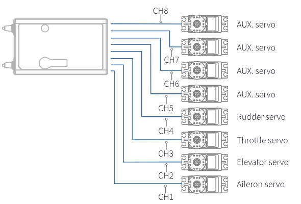
3.2Installing Receiver and Servo
Install the receiver and servo in the following methods:
4Operation Guide
After setting up, follow the instructions below to operate the system.
4.1Power-On
Follow the steps below to turn on the transmitter:
- Check to make sure that the battery is fully charged and installed correctly.
- Press and hold the power switch until the screen lights up.
- Power on the receiver.
- Operate with caution in order to avoid damage or injury.
- For your safety, please turn the transmitter switch and throttle to the safe position.
Note:
- If the SWA/SWB/SWC/SWD switch is not set to the highest position and the throttle stick is not set to the lowest position, the prompt message "PLEASE TURN SWA/SWB/SWC/SWD TO THE HIGHEST POSITION, THROTTLE TO THE LOWEST POSITION!" will appear, then set the switch or the stick to the correct position before starting the transmitter.
- After power-on, the system will pop up a window to prompt whether to set up failsafe for the current model. To disable the failsafe setting prompt, tap [CANCEL] or turn off the [FAILSAFE PROMPT] via [BOOT SETTINGS].
4.2LED
This LED is a multi-color indicator. It displays in a variety of colors such as red, green, blue, yellow, cyan, purple, white, and dazzling colors. You can set a color as required. You may set it to none. In addition, you may set it to display the electricity level. The brightness of LED can also be adjusted via TX SET > SYSTEM SETTINGS > LED.
Follow the steps below to perform the settings:
- Power on the transmitter. Press MENU to enter the function menu. Select TX SET (Transmitter Settings) and then press Scroll Wheel to enter.
- Select SYSTEM SETTINGS and press Scroll Wheel to enter the system settings menu. Scroll the Scroll Wheel to select LED COLOR and press Scroll Wheel, the selected item is flashing now.
- Scroll the Scroll Wheel to select the appropriate item and press Scroll Wheel. Press EXIT to save and exit.
4.3Binding
The transmitter and the receiver have been pre-bound before delivery. If you need to use other receivers, follow the steps below to bind the transmitter and the receiver. The transmitter supports both 2 Way and 1 Way binding, and 2 Way binding is the default setting. The transmitter will display the information returned by the receiver after the 2 Way binding is completed. Before binding, it is necessary to set RF System, RF Standard, Output Mode, and Frequency according to the actual application scenario.
[RF SYSTEM] Two modes are available: ROUTINE and FAST. For [ROUTINE], it presents strong anti-interference performance against other devices; for [FAST], it provides better coexistence with lower latency and power consumption.
[OUTPUT] Two combined output options are available, including four output modes, namely PWM/S.BUS, PPM/i-BUS, PWM/i-BUS and PPM/S.BUS. Choose according to your needs. Using the FS-ST8 transmitter and FS-SR8 receiver for binding as an example:
- When the [OUTPUT] is set to PWM/S.BUS, connectors such as CH1 output PWM signals, and the SERVO connector outputs S.BUS signals.
- When the [OUTPUT] is set to PPM/i-BUS, the CH1 connector outputs PPM signals, other channel connectors have no output, and the SERVO connector outputs i-BUS signals.
- When the [OUTPUT] is set to PWM/i-BUS, connectors such as CH1 output PWM signals, and the SERVO connector outputs i-BUS signals.
- When the [OUTPUT] is set to PPM/S.BUS, the CH1 connector outputs PPM signals, other channel connectors have no output, and the SERVO connector outputs S.BUS signals.
Note: Regardless of which type the receiver's [OUTPUT] is set to, the SENS connector will output the i-BUS-in signal.
[FREQUENCY] To set an appropriate frequency according to your servos.
- When the frequency value is set to 50Hz, it presents the analog servo, and set to 333Hz, it is for digital servo. For other servo, set the value in the range between 50 and 400Hz.
After the above settings, complete ANT 2 Way binding following the steps below:
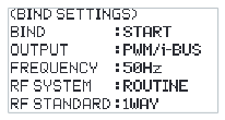
- Scroll the Scroll Wheel to navigate to the START and press the Scroll Wheel to put the transmitter into bind mode.
- Press and hold the BIND button of the receiver while powering on the receiver, the LED of the receiver should be flashing, indicating that the receiver is in bind mode. For other binding ways, please refer to the FS-SR8 receiver manual.
- After the binding process is completed, the LED of the receiver stops flashing and is solid on.
- Check to make sure the transmitter and the receiver are working correctly, if there are any issues or unexpected operation arise, follow the steps above to bind again.
Note: If the transmitter that has its RF standard set to 1Way enters bind mode, put the transmitter to exit binding state when the status of the receiver LED changes to slow flash, and at the same time, the receiver LED is solid on, indicating that the binding is completed.
- Different receivers have different bind procedures. For more information visit the FLYSKY website for manuals and other related information.
- Product information is updated regularly, please visit our website for more information.
4.4Stick Calibration
The calibration is required in case of data offset of the transmitter due to physical wear in long-term operations. At this time, we need to calibrate the output data and neutral angle of the stick, throttle trigger, and potentiometers.
The transmitter has been calibrated at the factory. If you need to recalibrate it, please follow the steps below to perform the settings:
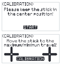
- Power on the transmitter, enter the TX SET menu, and select the CALIBRATION function. Follow the prompts to press the START for calibration.
- Swing the sticks to the maximum and minimum travel range in each direction respectively and then release them.
- Tap CALIBRATION to exit the calibration interface. The calibration is finished.
Note: If the pop-up window indicates that the calibration has failed, it means that the control to be calibrated has not reached the maximum and minimum travel range, the recalibration is required.
4.5Power-Off
Follow the steps below to turn off the system:
- Disconnect the receiver power.
- Press and hold the power switch for a time to turn off the transmitter.
- Make sure to disconnect the receiver power before turning off the transmitter. Failure to do so may lead to damage or serious injury.
5Main Interface
Instructions are about the main menu.
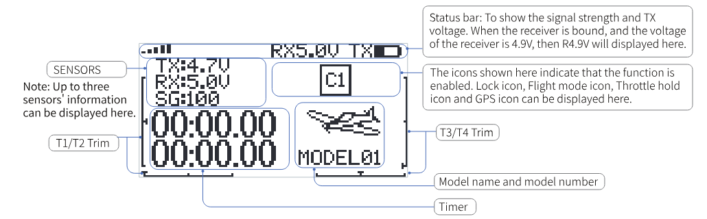
Quick access to the menu:
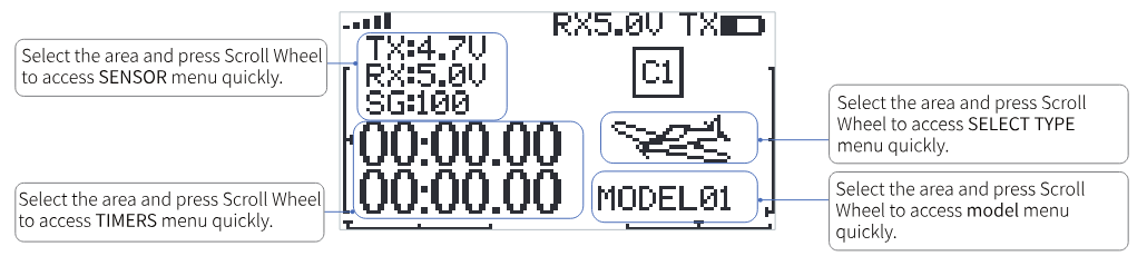
- Select the sensor area and press Scroll Wheel to access SENSOR menu quickly.
- Select the timer area and press Scroll Wheel to access TIMERS menu quickly.
- Select the model icon and press Scroll Wheel to access SELECT TYPE menu quickly.
- Select the model name and press Scroll Wheel to access model menu quickly.
6Function Menu
Note: This function was updated in version 1.0.57.
In this transmitter, we have classified the functions and made a new layout. There are 4 categories in icons in total. That is: TX SET (Transmitter Settings), RX SET (Receiver Settings), MDL SET (Model menu), GENER MENU (General menu). After the classification, it will become more convenient and easy to set up the model.
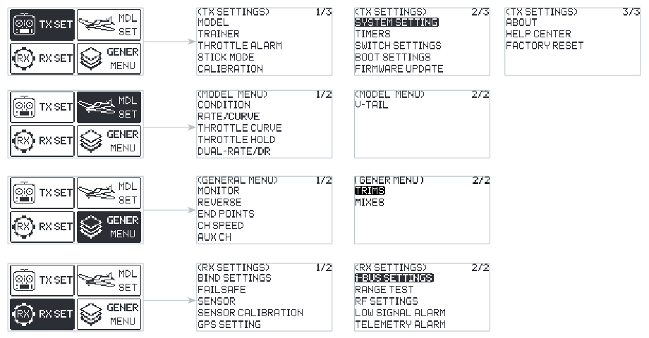
The next-level menu may vary with different model type, and lists below:
- For DELTA-WING: CONDITION, RATE/CURVE, THROTTLE CURVE, THROTTLE HOLD, DUAL-RATE/DR and DELTA-WING MIX;
- For FIXED-WING: CONDITION, RATE/CURVE, THROTTLE CURVE, THROTTLE HOLD, DUAL-RATE/DR and V-TAIL;
- For MULTICOPTER: CONDITION, RATE/CURVE, THROTTLE CURVE, THROTTLE HOLD and DUAL-RATE/DR;
- For ENGINEERING VEHICLE: CONDITION, RATE/CURVE, THROTTLE CURVE, THROTTLE HOLD, DUAL-RATE/DR and TRACK MIX;
- For ROBOT: CONDITION, RATE/CURVE, THROTTLE CURVE, THROTTLE HOLD, DUAL-RATE/DR and TRACK MIX;
- For GLIDERS: CONDITION, RATE/CURVE, THROTTLE CURVE, THROTTLE HOLD, DUAL-RATE/DR and V-TAIL;
- For HELICOPTERS: CONDITION, RATE/CURVE, THROTTLE CURVE, THROTTLE HOLD, DUAL-RATE/DR, PITCH CURVE, GYROSCOPE1 and GYROSCOPE2;
- For BOAT: CONDITION, RATE/CURVE, THROTTLE CURVE, THROTTLE HOLD and DUAL-RATE/DR;
- For CAR: CONDITION, RATE/CURVE, THROTTLE CURVE, THROTTLE HOLD and DUAL-RATE/DR.
Function settings:
In the main interface, press MENU to enter the function menu. Select the function category by scrolling Scroll Wheel. Press Scroll Wheel to enter the corresponding next-level menu.
6.1Transmitter Settings
Note: This function was updated in version 1.0.57.
There are thirteen function menus in TX SET menu: MODEL, TRAINER, THROTTLE ALARM, STICK MODE, CALIBRATION, SYSTEM SETTINGS, TIMERS, SWITCH SETTINGS, BOOT SETTINGS, FIRMWARE UPDATE, ABOUT, HELP CENTER, and FACTORY RESET.
In the main menu, press MENU to enter the function menu. Select TX SET by scrolling Scroll Wheel and press Scroll Wheel to enter.
6.1.1TX SET - MODEL
Note: This function was updated in version 1.0.57.
The MODEL menu is used for model management. It includes seven options: MODEL SELECT, MODEL NAME, MODEL COMB., SELECT TYPE, MODEL COPY, MODEL RESET and RACE MODE.
MODEL SELECT
The transmitter can save up to 10 sets of model data, and you can call out one set of model data at any time and use it as needed.
MODEL NAME
The name of the model you select can be edited and changed.
MODEL COMB.
Allows the selection of multiple model combinations and the presetting of a switch. When the selected model combination includes the current model, the preset switch can be used to switch between models.
Only specific position switches can be assigned, and only the assigned positions are effective.
For example, if the switch position is assigned to "up", the model can be switched only when the switch is moved to the "up" position. Other positions (e.g., "down" or "middle") will have no effect.
SELECT TYPE
To provide a total of 9 different types of models, and it covers most of kinds of the models.
MODEL COPY
If you have a new model that is the same or similar to the model you used before, you can use this function to make a copy for quick setting.
MODEL RESET
It means that this function will reset all the set values of the model parameters and restore the factory settings.
RACE MODE
This function is used to quickly disable the LOW SIGNAL ALARM and TELEMETRY ALARM, effectively turning off the related signal alarms. It is recommended to use this function to disable the low signal alarm and telemetry loss alarm before the race; after the race, you can decide whether to re-enable these two alarm functions based on the actual usage scenario.
Function settings:
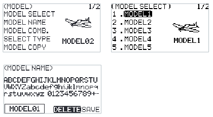
- In the MODEL menu, select the function by scrolling Scroll Wheel and press Scroll Wheel to enter the corresponding next-level menu.
- In the MODEL SELECT menu, scroll Scroll Wheel to select an appropriate model and press Scroll Wheel to confirm, then press EXIT to save.
- In MODEL NAME menu, scroll Scroll Wheel to select an appropriate alphabet or number. Use DELETE to delete the related characters. To save the settings by pressing Scroll Wheel while SAVE is in selecting state. It supports up to 8 characters.
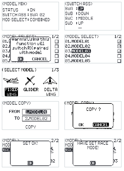
- If [MODEL COMB.] is selected: Choose STATUS > ON. Select SWITCH ASS, then press the scroll wheel to enter the setup menu. In the menu, select the desired control or toggle the corresponding physical control. After selecting MOD SELECT, proceed to the next menu level: Choose the models to be combined. The system will display a confirmation prompt. Select OK to confirm.
- In SELECT TYPE menu, scroll Scroll Wheel to select an appropriate type and press Scroll Wheel to finish.
- In MODEL COPY menu, scroll Scroll Wheel to select the model for FROM and TO respectively, then select COPY and press Scroll Wheel, a pop-up menu come along with it. Select OK and press Scroll Wheel to confirm. Press EXIT to save and exit.
- For MODEL RESET, select OK and press Scroll Wheel to confirm in the pop-up menu appeared.
- If you select RACE MODE and the system will pop up a message, select OK and press Scroll Wheel to close the pop-up window, meaning the relevant alarms have been disabled. If you select RACE MODE again, a pop-up message will indicate that the system is already in race mode; select OK and press Scroll Wheel to close the pop-up window.
Note: When the RF system is enabled:
- If the receiver is not communicating with the transmitter and RACE MODE is selected, the RF STANDARD will automatically adjust to 1WAY, and the RF SYSTEM will switch to ROUTINE.
- If the receiver is in 1way communication with the transmitter and RACE MODE is selected, the RF SYSTEM will switch to ROUTINE.
6.1.2TX SET - TRAINER
Note: This function was updated in version 1.0.57.
This function is designed for beginners. The trainer can make instruction and training for the students under supervision, to avoid the risks caused by beginners in the learning process.
It features TRAINER mode and STUDENT mode, and a switch can be set to enable or disable the trainer function. When the switch is set to ON, the trainer controls the aircraft, and the student controls the aircraft when the switch is set to OFF.
For example, if the trainer and the student use two FS-ST8 transmitters for teaching and training. After connecting the two transmitters via the FlySky's trainer cable, set the MODE of the trainer transmitter to TRAINER, as well as setting a control switch. Then set the MODE of the student transmitter to STUDENT.
The FS-ST8 can also realize the trainer function with the FS-WTM01 wireless trainer unit and other FlySky transmitters, such as PL18 transmitter. Set the transmitter which has physically connected to the FS-WTM01 as the trainer transmitter.
Function settings:
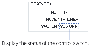
- Select TRAINER and press Scroll Wheel to enter.
- Set ON or OFF to turn on or turn off using Scroll Wheel.
- Set a switch. In the menu, select a switch and its corresponding position to finish, or you can toggle the corresponding physical switch on the transmitter to finish.
Notes:
- Use a trainer cable to connect the two transmitters which are for the trainer and the student. Make sure the trainer cable connected well before using this function.
- VALID will be displayed on the top of this menu, when the switch assigned is set to on and the signal of the student transmitter is input. Namely, the trainer function is valid; otherwise, the function is invalid.
6.1.3TX SET - THROTTLE ALARM
Note: This function was updated in version 1.0.57.
This function is used to monitor the throttle position.
You can set the trigger value and activation status for the alarm. When the throttle stick crosses the set position, the system will emit a beep sound as an alarm.
Function settings:
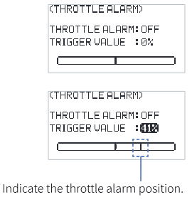
- Select THROTTLE ALARM and press Scroll Wheel to enter.
- Set THROTTLE ALARM: OFF. It can be toggled between ON and OFF.
- Select TRIGGER VALUE, scroll the wheel to set the appropriate value, and press the wheel to confirm.
Note: If the alarm sound is turned off (SYSTEM SETTING > SOUND/VOLUME), the alarm sound will not be triggered even if it is enabled here.
6.1.4TX SET - STICK MODE
The transmitter provides four stick modes, you can set it according to your habit. CH1 represents Aileron, CH2 represents Elevator, CH3 represents Throttle, CH4 represents Rudder.
Function settings:
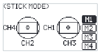
- Select STICK MODE and press Scroll Wheel to enter.
- Select an appropriate item by scrolling Scroll Wheel and press Scroll Wheel to finish.
- Test the function to confirm all the channel direction is the same as the actually expected direction.
- The mechanical structure may adjust as needed after the mode is selected. Namely, the throttle needs to be adjusted from self-centering to non-self-centering and vice versa. In addition, in the mode of throttle non self-centering, the throttle position should be adjusted when it is from left to right and vice versa. For other changes, the adjustment is not required.
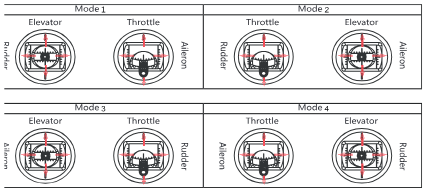
Mode 2 (M2) is the default mode. Changing between modes 2/4 (M2/M4) and modes 1/3 (M1/M3) will necessitate changing the throttle gimbals position. You need to open up the product, see 8.3 Swapping Gimbals for details.
6.1.5TX SET - SYSTEM SETTING
Note: This function was updated in version 1.0.57.
The system setting function is used to configure the transmitter system. It includes the following options: SOUND, VOLUME, ALARM TIME, VIBRATION, GRADE, BATTERY TYPE, LED COLOR, LED BRIGHTNESS, CONTRAST, BACKLIGHT TIME, and AUTO SHUTDOWN.
| SOUND | To set the sound for system and alarm. SYS+ALA means the same sound for system and alarm. |
| VOLUME | To set the volume of the sound. |
| ALARM TIME | To set the time of the idle alarm or whether to enable the idle alarm function. |
| VIBRATION | To set the vibration of the system and alarm. SYS+ALA means the same vibration for system and alarm. |
| GRADE | To set the vibration grade of the system and alarm. |
| BATTERY TYPE | To set the battery type. |
| LED COLOR | To set the color of the LED. |
| LED | To set the brightness of the LED. |
| BRIGHTNESS | To set the brightness of the LCD. |
| CONTRAST | To set the contrast of the LCD. |
| TIME | To set the time of the backlight, namely how long the screen takes to turn off when not in use. |
| AUTO SHUTDOWN | To set the time of auto shutdown or turn off it. |
Notes:
- Leaving the screen on for longer will use more power and as such may lead to reduced battery time.
- If the transmitter enters sleep mode, you can exit sleep mode by operating the scroll wheel, MENU button, EXIT button, or power button.
Function settings:
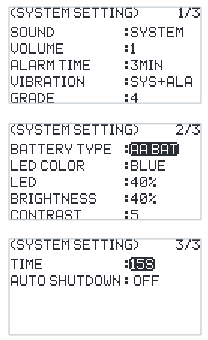
- Select SYSTEM SETTING and press Scroll Wheel to enter.
- Select a function you want to set and press Scroll Wheel, the selected box is flashing now.
- Select an appropriate item and press Scroll Wheel to finish. Press EXIT to save the settings and exit.
6.1.6TX SET - TIMERS
The Timer function is used for timing in races, including count up and countdown. You can also use it to test a tank of fuel or a full battery and confirm the usage time. The transmitter provides two timers, which can be set independently to achieve different timing functions. Start, stop and reset switches can be set to enable, disable or reset the timer by the switch. The timer alarm time can also be set. After setting the time, the system will send an alarm for reminder 10 seconds prior to the expiration. The main interface will display it after the timer is set.
Function settings:
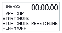
- Select TIMERS and press Scroll Wheel to enter.
- For TYPE, the selected box will be flashed when chosen. Select UP or DOWN. If DOWN is selected, you need to set the time using Scroll Wheel, then press EXIT to save it.
- Set switches to START, STOP and RESET using Scroll Wheel. You can also set a throttle trigger value to start the timer to calculate the working time of the throttle after the timer is on.
- For ALARM, set ON or OFF using Scroll Wheel. If an alarm is set, you need to set the alarm time using Scroll Wheel. Press EXIT to save it.
6.1.7TX SET - SWITCH SETTINGS
Used to set which controls can be assigned including SW class switches, Dials (Upgraded version), buttons on the back (Upgraded version) or Knobs.
Through this function, you can set the throttle mode for self-centering or non-self-centering by setting THRO. If you set to self-centering, the stick position is not prompted upon power-on. You can also set the number of channels of transmitter by setting CH NUM, and the range is 8 to 12.
Function settings:
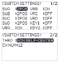
- Select SWITCH SETTINGS and press Scroll Wheel to enter.
- Select a control you want to set using Scroll Wheel.
- Select an appropriate item and press Scroll Wheel to confirm. Press EXIT to save the settings and exit.
Notes:
- You can set three-position switch to two-position switch via this function.
- In addition, you can set the position-level when the physical switch needs to be changed here.
6.1.8TX SET - BOOT SETTINGS
To enable or disable the switch self-check prompt function and failsafe setting prompt function in case of power-on.
Function settings:
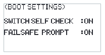
- Select BOOT SETTINGS and press Scroll Wheel to enter.
- Select SWITCH SELF CHECK and press Scroll Wheel, then set to ON or OFF using Scroll Wheel.
- Select FAILSAFE PROMPT and press Scroll Wheel, then set to ON or OFF using Scroll Wheel. Press EXIT to save the settings and exit.
6.1.9TX SET - FIRMWARE UPDATE
Used to update the firmware of the transmitter. When the firmware needs to be upgraded, it is needed to put the transmitter into upgrade mode using this function first.
Function settings:
- Download the latest firmware.
- Connect the transmitter and the PC via a USB Type-C cable. Open the firmware on a computer.
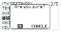
- At the transmitter side, select FIRMWARE UPDATE. The system will show a prompt menu, select OK and press Scroll Wheel to put the transmitter into updating mode. Click Update on the firmware screen on the computer.
Notes:
- Always ensure sufficient power supply for the transmitter when using this function. To avoid the receiver losing control, make sure to power off the receiver before starting this function.
- Don't disconnect the USB Type-C cable during the firmware updating, otherwise the transmitter may occur a fault.
- You can also upgrade the firmware through FLYSKYAssistant with Version 3.0 or later.
6.1.10TX SET - ABOUT
Used to display the system information, such as hardware version, etc.
Function settings:
Select ABOUT and press Scroll Wheel to enter, then you can view the related information.
6.1.11TX SET - HELP CENTER
To obtain the user manual via this function.
Function settings:
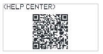
Select HELP CENTER and press Scroll Wheel to enter, then you can view the related information.
6.1.12TX SET - FACTORY RESET
Used to restore the entire transmitter system to the factory settings in case a number of parameters are adjusted incorrectly during operation. Reset all data of the model current in use. All other models are reset except MDL SET, MODEL TYPE and MODEL NAME.
Function settings:
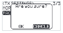
- Select FACTORY RESET and press Scroll Wheel to enter, then a pop-up menu appears.
- Select OK and press Scroll Wheel to finish.
6.2Model Settings
Note: This function was updated in version 1.0.57.
Used to set the functions related to the model. The functions vary with different models. All functions are CONDITION, RATE/CURVE, THROTTLE CURVE, THROTTLE HOLD, DUAL-RATE/DR, PITCH CURVE, HELI PITCH SETUP, GYROSCOPE, DELTA-WING MIX, V-TAIL and TRACK MIX.
In the main interface, press MENU to enter the function menu. Select MDL SET by scrolling Scroll Wheel and press Scroll Wheel to enter.
6.2.1MDL SET - CONDITION
Note: This function was updated in version 1.0.57.
For some advanced users, there may be several different requirements when flying the same model. For example, some players set their model airplane to a specific condition for takeoff, increasing the channel action to handle various uncertainties during the takeoff process. They then switch to another condition for normal flight. For F3A models, you need to adjust each action to be smaller and smoother to achieve more accurate movements.
A switch can be assigned to switch between these conditions. There are three conditions available, with the following priority levels: Condition 3 has the highest priority, while Condition 1 has the lowest priority.
Function settings:
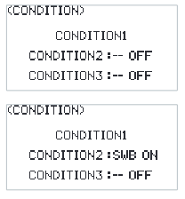
- Select CONDITION and press Scroll Wheel to enter.
- Select an item you want to set and press Scroll Wheel to enter the next level menu. Assign a switch/knob to switch condition.
6.2.2MDL SET - RATE/CURVE
Note: This function was updated in version 1.0.57.
This function can be divided into two parameters. Firstly, the rate can be quickly adjusted in different states to set the output value of certain channels. The adjustment includes symmetrical treatment at both ends of the range. In different states, you can set different output values to achieve the best control effect. The rate function can be used to set CH1, CH2, and CH4. The output data can be adjusted within the range of 0 to 100%.
Secondly, the curve is set according to different flight effect requirements. For example, in F3C, delicate and smooth operations are needed for flight actions. The curve data can be adjusted from 0 to 100%. The larger the data, the more delicate the control becomes by reducing median sensitivity. Conversely, the lower the data, the more coarse the control action becomes by increasing median sensitivity (down to -100%). These settings can be used for special 3D maneuvers.
Function settings:
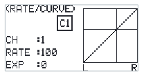
- Select RATE/CURVE and press Scroll Wheel to enter.
- Select CH and press Scroll Wheel, then select a channel you want to set and press Scroll Wheel to confirm.
- Select RATE and press Scroll Wheel, then select a value you want to set and press Scroll Wheel to confirm.
- Select EXP and press Scroll Wheel, then select a value you want to set and press Scroll Wheel to confirm.
- Press EXIT to save the settings and exit.
6.2.3MDL SET - THROTTLE CURVE
Note: This function was updated in version 1.0.57.
It is a function specifically for throttle channel to achieve the perfect match between throttle output and motor or engine. It can be set individually in different flight conditions, with 7 dynamic adjustment points throughout the travel. You can set freely to achieve the best control effect on the throttle.
Function settings:
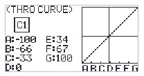
- Select THROTTLE CURVE and press Scroll Wheel to enter.
- Select a point you want to set and press Scroll Wheel, then select a value you want to set and press Scroll Wheel to confirm. Press EXIT to save the settings and exit.
6.2.4MDL SET - THROTTLE HOLD
Note: This function was updated in version 1.0.57.
This is a common function used for adjustment and trimming. It is also used before take-off and during landing to maintain the normal output of other channels while completely locking the throttle channel output. This ensures a safe working state. You can enable the function, set the status switch, or set the lock position as needed.
Function settings:
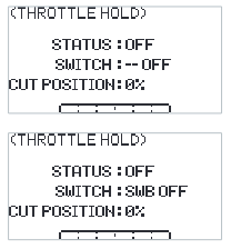
- Select THROTTLE HOLD and press Scroll Wheel to enter.
- Set ON or OFF to turn on or turn off using Scroll Wheel.
- Set a switch. In the menu, select a switch and its corresponding position to finish, or you can toggle the corresponding physical switch on the transmitter to finish.
- Set CUT POSITION, select an appropriate value then press Scroll Wheel. Press EXIT to save the settings and exit.
6.2.5DUAL-RATE/DR
Note: This function was added in version 1.0.57.
To set the DUAL-RATE/DR function, switch, and effective condition. The transmitter supports 4 sets of DUAL-RATE/DR settings. When 2 or more sets of DUAL-RATE/DR settings are assigned to the same channel and all are enabled, the one that is placed later has a higher priority.
After enabling this function, the DUAL-RATE/DR icon will be displayed on the corresponding interface.
Function settings:
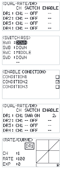
- Select DUAL-RATE/DR and press Scroll Wheel to enter.
- Select CH and press the scroll wheel to set the desired channel.
- Select SWITCH and press the scroll wheel to enter the settings menu. Choose the control or toggle the corresponding physical control.
- Select ENABLE and press the scroll wheel to enter the ENABLE CONDITION interface. Choose the condition you want to enable, then press EXIT to save the settings and exit.
6.2.6MDL SET - V-TAIL
This function is designed for specific aircraft models, such as fixed-wing aircraft with V-tails. It allows you to perform mixing control for both channels in the same direction or in the reverse direction.
Function settings:
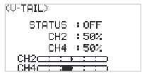
- Select V-TAIL and press Scroll Wheel to enter.
- Set ON or OFF to turn on or turn off using Scroll Wheel.
- Select the channel and select an appropriate value then press Scroll Wheel. Press EXIT to save the settings and exit.
- Carry out a test to confirm that the transmitter functions normally after it is set.
6.2.7MDL SET - DELTA-WING MIX
This function is designed for specific aircraft models, such as delta-wing aircraft with two ailerons. Use this function to make the ailerons perform as elevators.
Function settings:
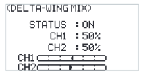
- Select DELTA-WING MIX and press Scroll Wheel to enter.
- Set ON or OFF to turn on or turn off using Scroll Wheel.
- Select the channel and select an appropriate value then press Scroll Wheel. Press EXIT to save the settings and exit.
- Carry out a test to confirm that the transmitter functions normally after it is set.
6.2.8MDL SET - TRACK MIX
This function is designed for specific models, such as tank and excavator models. The two tracks can be driven in the same direction or in reverse directions. In these cases, the track mixed control function can be used.
By default, CH1 and CH2 are assigned. You can assign CH1 and CH2 to controls such as knobs VRA and VRB, or dials VRC and VRD (Upgraded version) by setting the GENER Menu > AUX CH.
You can use CH1 control for reverse motion and differential steering, that is, turning left or right. Additionally, you can use CH2 control for forward and backward movement.
Function settings:
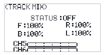
- Select TRACK MIX and press Scroll Wheel to enter.
- Select STATUS and press Scroll Wheel.
- Select an item and select an appropriate value then press Scroll Wheel. Press EXIT to save the settings and exit.
- Carry out a test to confirm that the transmitter functions normally after it is set.
6.2.9MDL SET - PITCH CURVE
Note: This function was updated in version 1.0.57.
This function is set for some specific models, for example, helicopter models. Adjust the helicopter's pitch motion curve to match the throttle output to achieve the best flight status of the helicopter.
Function settings:
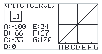
- Select PITCH CURVE and press Scroll Wheel to enter.
- Select a point you want to set and press Scroll Wheel, then select an appropriate value and press Scroll Wheel to confirm. Press EXIT to save the settings and exit.
6.2.10MDL SET - GYROSCOPE1
Note: This function was updated in version 1.0.57.
To set the value of the gyroscope and whether to enable the function.
| STATUS | To turn the gyroscope to on or off. |
| CH | Assign the channel to output gyroscope signal. CH5 or CH7 ~ CH12 can be assigned. CH5 is the default channel; after setting, the channel will display in the lower part of the screen. |
| CONTROL | To set a control to control gyroscope channel. |
| MID (neutral) | The neutral value of the control. The range is from -100% to +100%, 0% is the default value. |
| RANGE | This item appears and can be set after a control is assigned. To set the range of the control. The range is from 0% to 100%, 20% is the default value. |
| STEP | This item appears and can be set after the control is set to KEY1+KEY2. Then you can set the step value, the range is from 1 to 100, 2 is the default value. |
Note:
- By default, KEY1 is used to decrease the value and KEY2 is used to increase the value. You can change it via REVERSE function, namely, after the reverse, KEY1 is to increase the value and KEY2 is to decrease the value.
- The assigned channels for Gyroscope 1 and Gyroscope 2 channels must be different.
- When the gyroscope function is enabled, if the channel assigned by this function is reassigned in AUX CH function, the settings assigned in AUX CH function will be invalid.
Function settings:
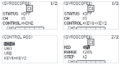
- Select GYROSCOPE and press Scroll Wheel to enter.
- Select STATUS and press Scroll Wheel, then set to ON or OFF using Scroll Wheel.
- Select CH and press Scroll Wheel, then set an appropriate channel.
- Then set the CONTROL, MID (neutral), RANGE and STEP. Press EXIT to save the settings and exit.
6.2.11MDL SET - GYROSCOPE2
Note: This function was updated in version 1.0.57.
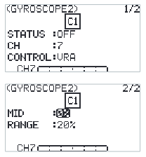
The function setting is the same as that of Gyroscope 1, but the output channels for Gyroscope 1 and Gyroscope 2 must be different.
6.3General Settings
Used to set or adjust the general functions which are commonly used including MONITOR, REVERSE, END POINTS, CH SPEED, AUX CH, TRIMS and MIXES.
In the main interface, press MENU to enter the function menu. Select GENER MENU by scrolling Scroll Wheel and press Scroll Wheel to enter.
6.3.1GENER MENU - MONITOR
To display the real time output status of all channels, you can monitor the current output status of all channels.
Function settings:
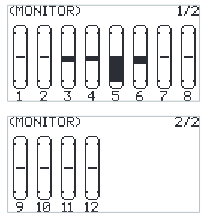
Select MONITOR and press Scroll Wheel to enter the monitoring menu. Then view the channel information.
Note: There is another hidden function on menu: Channel test. Press and hold the Scroll Wheel in this menu. The system will prompt "Confirm access channel test?". Select OK and press Scroll Wheel to enter. All channels will be output in one direction. It is convenient to detect whether the corresponding channel is normal. This function can also be used in the distance test.
- To avoid accidents, do not activate channel test function when the transmitter is connected with the models or the engines of the model is started.
6.3.2GENER MENU - REVERSE
You can perform the reverse processing of the output data of one channel or more channels. This function is used in the debugging of a model.
Models may follow different standards in the design. In the assembly and debugging of a model, if you find that the operation model is opposite to the required direction, for example, the model goes to the left when you want the right direction, the output signal direction of the transmitter needs to be adjusted at this time. The function is used to adjust the action direction of output signals of each channel.
Function settings:
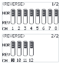
- Select REVERSE and press Scroll Wheel to enter.
- Select a channel you want to set and press Scroll Wheel to set NOR (normal) or REV (reverse). Press EXIT to save the settings and exit.
- Carry out a test to confirm that the directions of servos are same as your required direction.
6.3.3GENER MENU - END POINTS (Including SUBTRIM)
Adjust the travel amount of the servo output. This function is used in debug. This function can be used to set the travel of the HIGH, LOW and SUBTRIM at both ends of the channel respectively.
When the model is designed, there are changes in the size of the structure and the specification may not be unified. In addition, there may be different sizes of operator's habitual actions. The servo travel function can be used to set the travel amount required for each channel to adjust the corresponding structure for the best match, to obtain the required operation effect. For example, you want to operate that the turning action is not so large, you can adjust the value of the direction channel at both ends to be smaller. In this way, the turning action should be smaller, with less likely to be tailspin.
Function settings:
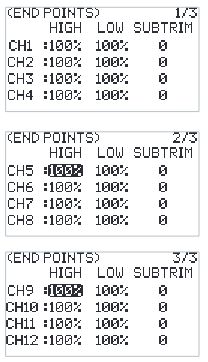
- Select END POINTS and press Scroll Wheel to enter.
- Select an item you want to set, select an appropriate value then press Scroll Wheel. Press EXIT to save the settings and exit.
6.3.4GENER MENU - CH SPEED
Note: This function was updated in version 1.0.57.
This function can be used to adjust the output speed of some channels for a specific model. For example, in the landing gear retraction, users may want it to be opened slowly, therefore, you can slow down the output speed of the corresponding channel.
Function settings:
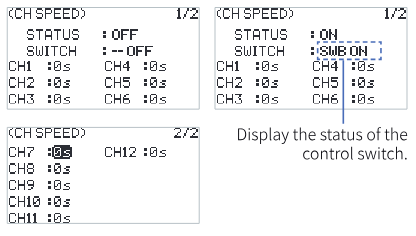
- Select CH SPEED and press Scroll Wheel to enter.
- Set ON or OFF to turn on or turn off using Scroll Wheel.
- Set a switch. In the menu, select a switch and its corresponding position to finish, or you can toggle the corresponding physical switch on the transmitter to finish.
- Set a speed value. Press EXIT to save the settings and exit.
6.3.5GENER MENU - AUX CH
Note: This function was updated in version 1.0.57.
For some models with complex functions, we provide up to 12 channels of output, 8 of which are auxiliary channels for the most effective control of multiple functions in different ways. The AUX CH (auxiliary channel) function is used to set the control settings for CH5 to CH12, assigning the controls to the channels for operation.
Function settings:
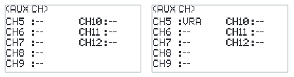
- Select AUX CH and press Scroll Wheel to enter.
- Select an auxiliary channel and press Scroll Wheel to enter the switch assigned menu.
- Set a switch. Press EXIT to save the settings and exit.
6.3.6GENER MENU - TRIMS
To set the step value of the trims.
Function settings:
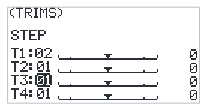
- Select TRIMS and press Scroll Wheel to enter.
- Select a trim you want to set and press Scroll Wheel.
- Select an appropriate value then press Scroll Wheel. Press EXIT to save the settings and exit.
6.3.7GENER MENU - MIXES
Note: This function was updated in version 1.0.57.
MIXES is enabled for some models that require two channels to act in linkage. For example, you can perform rudder compensation so that the aircraft will not lift its nose when throttling up. This transmitter provides up to 8 groups of mixes.
| STATUS | To set whether to enable the function. |
| SWITCH | To set a switch which is to control the MIX. |
| M (Master) | To set a master channel, this channel will control the slave channel. |
| S (Slave) | To set a slave channel, this channel will be controlled by the master channel. |
| NOR (Normal) | To set how much the slave channel will move when the master channel moves in HIGH end. The adjustment range is from -100% to 100%. If the value is set to 50%, when the output of the master channel is 100%, the output of the slave channel is 50% at the time. |
| REV (Reverse) | To set how much the slave channel will move when the master channel moves in LOW end. The adjustment range is from -100% to 100%. If the value is set to 50%, when the output of the master channel is -100%, the output of the slave channel is -50% at the time. |
| OFFSET | To set the offset value of the slave channel. |
Function settings:
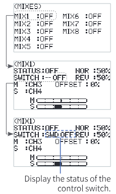
- Select MIXES and press Scroll Wheel to enter.
- Set ON or OFF to turn on or turn off using Scroll Wheel.
- Set a switch. In the menu, select a switch and its corresponding position to finish, or you can toggle the corresponding physical switch on the transmitter to finish.
- Set a channel for M or S using Scroll Wheel.
- Set appropriate values for NOR, REV and OFFSET using Scroll Wheel.
- Press EXIT to save the settings and exit.
6.4Receiver Settings With INT RF
Note: This function was updated in version 1.0.57.
The RX SET (receiver setting) menu provides a number of function setting menus to allow you to set up the receiver system in all aspects. That is, BIND SETTINGS, FAILSAFE, SENSOR, SENSOR CALIBRATION, GPS SETTINGS, i-BUS SETTINGS, RANGE TEST, RF SETTINGS, LOW SIGNAL ALARM and TELEMETRY ALARM.
In the main menu, press MENU to enter the function menu. Select RX SET by scrolling Scroll Wheel and press Scroll Wheel to enter.
6.4.1RX SET - BIND SETTINGS
For function settings, refer to 4.3 Binding for details.
6.4.2RX SET - FAILSAFE
Note: This function was updated in version 1.0.57.
Failsafe is an important safety setting. It can be used to protect the model from loss or reduce the degree of loss when the receiver loses signal without control. In addition, it plays a role in protecting personnel safety.
You can set the data in case of out-of-control for all output channels.
The failsafe judgment time can be configured within a range of 250ms to 1000ms. By default, this time is set to 700ms for gliders, helicopters, delta wings, fixed-wing aircraft, and multicopters. For engineering vehicles, boat models, car models, and robots, the default failsafe judgment time is 300ms.
Function settings:
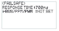
- Navigate to the Main Menu > MENU button > RX SET, then select FAILSAFE. Press the scroll wheel to enter the failsafe settings interface.
- Select FAILSAFE JUDGMENT TIME and press the scroll wheel. The option box will start blinking. Scroll the wheel to set the desired value, then press the scroll wheel to confirm.
For i-BUS/PPM/PWM signal. The FS-ST8 system supports three options including NOT SET, NONE or ON.
- NOT SET: The failsafe has not been set, and there is no output in case of out-of-control.
- NONE: It is no output for i-BUS/PPM/PWM channel.
- ON: i-BUS/PPM/PWM channel output respectively the set value. Namely, you can set a value respectively for each channel from 1 to 12. By default, this value is the reading of current channel output value.
Function settings:
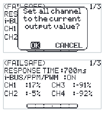
- Navigate to the Main Menu > MENU button > RX SET, then select FAILSAFE. Short press the scroll wheel to enter the failsafe settings interface.
- Set all channels: Select ON and short press the scroll wheel. The system will pop up a prompt interface. Adjust the corresponding controls to the desired positions and hold them if necessary. Select OK on the pop-up prompt interface and short press the scroll wheel again. The failsafe setting for all channels is completed.
- Set an individual channel (if needed): Select the channel you wish to configure and short press the scroll wheel. Choose the appropriate value or adjust the corresponding control to the desired position and hold it. Short press EXIT to save the settings and exit.
Notes:
- Because the S.BUS signal contains the failsafe flag bit, the receiver can transmit the "Failsafe State" information to the subsequent device through the failsafe flag bit, instead of using OFF. The subsequent device can make response accordingly by parsing the failsafe flag bit information.
- For the signal PWM/PPM/i-BUS without the failsafe flag bit, it supports the settings of OFF in case of failsafe. The "Failsafe State" information is transmitted to the subsequent device through OFF state.
- Caution: Remove the propeller prior to the failsafe test.
6.4.3RX SET - SENSOR
As an interesting feature for two-way communication systems, sensors can be used to send back some information you need through the receiver.
The transmitter can support up to 15 different types of returned data to provide you with the feedback of seven basic parameters, i.e., TX VOL (TX voltage), RX VOL (RX voltage), BVD VOL (BVD voltage), SIGNAL (signal intensity), NOISE, SNR (noise rate) and RSSI.
Notes:
- For BVD function, it is used to detect an external power supply. It is recommended to use this function to monitor the battery voltage and give an alarm in case of a failure. To perform an alarm by setting alarm values for LOW and HIGH.
- The range for the BVD voltage detection is from 0 to 70.
- The ID number 0 represents the transmitter or the receiver's voltage, signal strength, RSSI, Noise, or SNR. And the ID number 2 represents the first external sensor connected to the receiver, and so on. There are up to 15 sensors can be connected. It supports i-BUS series sensors, such as FS-CAT01 (altitude), FS-CPD01 (speed / magnetic), FS-CPD02 (speed / optical), FS-CVT01 (voltage), FS-CTM01 (temperature) and FS-CGPS01 (GPS).
Function settings:
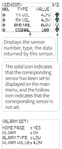
- Connect a sensor to the receiver via the SENS interface. At the transmitter side, select SENSOR and press Scroll Wheel to enter.
- Select an item you want to set using Scroll Wheel, such as TX VOL. Using Scroll Wheel, you can set it to display on the main menu, as well as set an alarm function and its alarm value corresponding to LOW and HIGH voltage. Press EXIT to save and exit.
The display of each sensor on the interface and main page is shown in the following table:
| Sensor | Abbrev. on Main Menu | INT RF | FRM303 | CRSF2 | PPM/S.BUS/CRSF |
|---|---|---|---|---|---|
| TX VOLT | TX | √ | √ | √ | √ |
| RX VOLT | RX | √ | √ | ||
| SIGNAL | ST | √ | √ | ||
| BVD VOLT | BV | √ | √ | ||
| RSSI | RS | √ | √ | √ | |
| SNR | SN | √ | √ | ||
| NOISE | NO | √ | √ | ||
| EXT VOLT | EV | √ | √ | ||
| TEMP | TM | √ | √ | ||
| Altitude | AT | √ | √ | ||
| REV | RV | √ | √ | ||
| GPS AT | GA | √ | √ | ||
| Distance | DS | √ | √ | ||
| Velocity | VG | √ | √ | ||
| RF VOLT | RV | √ | |||
| RF TEMP | RT | √ | |||
| FC VOLT | FV | √ | |||
| FC CUR | FC | √ | |||
| BAT CAP | BC | √ |
6.4.4RX SET - SENSOR CALIBRATION
This function is a special feature provided by FLYSKY. The setting allows you to make corrections to the parameters of some external sensors that need to be calibrated, so as to display the sensing data accurately. For example, for the external voltage sensor (BVD), after calibration, the displayed data will be closer to the real value.
Function settings:
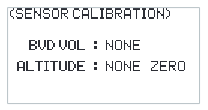
- Select SENSOR CALIBRATION and press Scroll Wheel to enter.
- Select an item you want to set using Scroll Wheel.
- Select an appropriate value and press Scroll Wheel to confirm. Press EXIT to save and exit.
6.4.5RX SET - GPS SETTING
This function needs to be used with the FS-CGPS01 GPS sensor of FLYSKY. You can view the information returned by GPS sensor after calibrating the GPS and setting an appropriate time. You can reset the start point when the displayed distance is inaccurate.
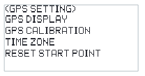
| GPS DISPLAY | When the GPS positioning is successful, you can check the information, such as whether the positioning is conducted, the number of satellites, DISTANCE, ALTITUDE, LONGITUDE, LATITUDE, etc. |
| GPS CALIBRATION | To calibrate the height value. |
| TIME ZONE | To set an appropriate time zone. After setting, you can view the date and time via GPS DISPLAY. |
| RESET START POINT | To reset the start point when the displayed distance is inaccurate. |
Function settings:
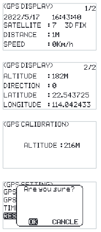
- Select GPS SETTING and press Scroll Wheel to enter.
- Select GPS DISPLAY and press Scroll Wheel to display the related information.
- Select GPS CALIBRATION and press Scroll Wheel to enter. Select CALIBRATION and press Scroll Wheel to start.
- Select RESET START POINT and press Scroll Wheel, the system will pop up a menu, select OK and press Scroll Wheel to finish.
6.4.6RX SET - i-BUS SETTINGS
This function is a unique and powerful serial communication protocol system provided by FLYSKY. It can be output to any channel by setting. For receivers with i-BUS interface and corresponding accessories, such as Serial Bus Receiver FS-CEV04. This function will be displayed when you set the OUTPUT to i-BUS mode via BIND SETTINGS function.
Function settings:
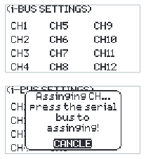
- The transmitter FS-ST8 and the receiver FS-SR8 are bound successfully. Connect the input cable of the Serial Bus Receiver FS-CEV04 to the SERVO interface of the receiver.
- At the transmitter side, select i-BUS SETTINGS and press Scroll Wheel to enter.
- Select a channel to be assigned, the system will show a prompt menu, if the channel is incorrect, select CANCEL to cancel.
- If the selected channel is about to assign to C1 channel of the Serial Bus Receiver FS-CEV04, then press the button K1 corresponding to C1 channel of FS-CEV04 receiver by a long thin tool, such as a thin tool which is tied with the Bind cable. After the setting is successful, the system will pop up a menu showing successful.
Note: If the receiver is overloaded, please supply power separately to prevent the wire from being burnt out due to excessive current.
6.4.7RX SET - RANGE TEST
Used to test whether wireless communication between the transmitter and the receiver is normal and the ambient radio interference.
As the actual remote control distance between transmitter and receiver is far away, it is difficult to make the transmitter and the receiver apart to several hundred meters to verify whether the RF module works normally. By using this function, the theoretical remote control distance can be reduced to 30-40 meters. When this function is enabled, it can test whether the transmitter and receiver are normal in a close distance, so as to save the test time.
Function settings:
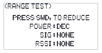
- Make sure the transmitter and the receiver are bound normally.
- Access the RANGE TEST interface and pull down the SWD button.
- One person stands in place with the model in hand, and the other person holds the transmitter and gradually moves away to 30-40 meters and walks around with this distance as a radius centered on this model.
- Make sure that the transmitter antenna is not blocked. The receiver antenna is placed at 90 degrees if there are two antennas, and there is no interference between the transmitter and the receiver in the open area.
- Observe the signal strength of the transmitter. If the signal strength is high and stable, it means that the radio frequency of this system works normally.
6.4.8RX SET - RF SETTINGS
This is an extended function option. The setting is used when the external RF module is needed. The EXT RF can be set to one of the following items: OFF, PPM.P, PPM.N, S.BUS, FRM303, CRSF and CRSF2, so as to be compatible with the external RF module with different protocol. When the external RF is set to CRSF2 or FRM303, the INT RF (local RF) is disabled.
When EXT RF is set to FRM303 to comply with FRM303 RF module, these functions can be set at the transmitter side: refer to 6.5 Receiver Settings With EXT RF (FRM303 RF MODULE) for details.
If it sets to CRSF, it supports the CRSF RF module.
If it sets to CRSF2, it supports the CRSF RF module, and the receiver bound with the transmitter can return RSSI as well. It can return flight control voltage, flight control current and battery capacity information.
Function settings:
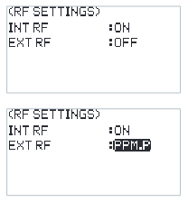
- Select RF SETTINGS and press Scroll Wheel to enter.
- Select an item you want to set using Scroll Wheel.
- Select an appropriate item and press Scroll Wheel to confirm. Press EXIT to save and exit.
Note: When the external RF is set to FRM303, the input signal of the FRM303 RF module should be set to open source protocol. To set it via the following steps: Push upwards the Up key of the five-way key for greater than or equal 3 seconds and less than 9 seconds while powering on the RF module, it enters the input signal setting state. And at the time, the LED in blue is solid on. Then push upwards the Up key or push downwards the Down key to switch the input signal. When the LED is working in four-flash-one-off mode repeatedly, it is indicating that it is the input protocol complied, then press the Center key for 3 seconds to save the settings. Push the Left key to let the FRM303 RF module to exit the signal setting state.
6.4.9RX SET - LOW SIGNAL ALARM
Note: This function was added in version 1.0.57.
This function is used to set up the alarm feature for signal strength when the transmitter and receiver communicate in two-way mode.
You can specify the alarm signal strength value, as well as whether to enable repeated alarms and set the time interval for repeated alarms. Additionally, the alarm sound and vibration can be enabled or disabled.
After setting the low signal alarm function, when the receiver's signal strength falls below the set value, the transmitter will trigger a low signal alarm according to the configured method.
Function settings:
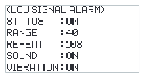
- Select LOW SIGNAL ALARM and press Scroll Wheel to enter.
- Select STATUS and press Scroll Wheel to toggle between ON or OFF.
- Select RANGE and press Scroll Wheel. The option box will begin to blink. Scroll the wheel to set the desired value, then press the scroll wheel to confirm.
- Select REPEAT and press Scroll Wheel. The option box will begin to blink. Scroll the wheel to set the desired value, then press the scroll wheel to confirm.
- Select SOUND and press the scroll wheel to toggle between ON or OFF.
- Select VIBRATION and press the scroll wheel to toggle between ON or OFF.
Note: If the alarm sound is turned off (SYSTEM SETTING > SOUND/VOLUME), the alarm sound will not be triggered even if it is enabled here.
6.4.10RX SET - TELEMETRY ALARM
Note: This function was added in version 1.0.57.
Used to set up the alarm function for telemetry loss when the transmitter and receiver communicate in two-way mode.
You can set the alarm trigger time and choose whether to enable or disable the alarm sound and vibration.
Function settings:
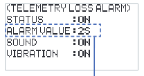
- Select TELEMETRY ALARM and press Scroll Wheel to enter.
- Select STATUS and press Scroll Wheel to toggle between ON or OFF.
- Select ALARM VALUE and press Scroll Wheel. The option box will begin to blink. Scroll the wheel to set the desired value, then press the scroll wheel to confirm. ALARM VALUE is used to indicate how long after telemetry loss the alarm should be activated. Note that if the connection is interrupted and then restored within the sensitivity time duration, the alarm will not be triggered.
- Select SOUND and press the scroll wheel to toggle between ON or OFF.
- Select VIBRATION and press the scroll wheel to toggle between ON or OFF.
Note: If the alarm sound is turned off (SYSTEM SETTING > SOUND/VOLUME), the alarm sound will not be triggered even if it is enabled here.
6.5Receiver Settings With EXT RF (FRM303 RF MODULE)
When EXT RF is set to FRM303 module, the settings for the receiving system include BIND SETTINGS, PORT PROTOCOL, FAILSAFE, PWM FREQUENCY, SIGNAL STRENGTH, SENSOR, GPS SETTING, RF SETTINGS and ABOUT RECEIVER.
Note that when using the FRM303 RF MODULE, the FGPZ03 RF adapter is required to connect the FRM303 to the FS-ST8 transmitter.
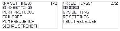
In the main menu, press MENU to enter the function menu. Select RX SET by scrolling Scroll Wheel and press Scroll Wheel to enter.
6.5.1RX SET - BIND SETTINGS
After the FRM303 RF module is connected to the FS-ST8 transmitter, it can be bound with the FlySky 3rd generation receiver (classic edition and enhanced edition).
If binding with the classic edition receiver, RF system can choose CLASSIC 18CH or C-FAST 10CH. And for the enhanced edition receiver, ROUTINE 18CH, FAST 8CH or LORA 12CH can be selected.
| CLASSIC 18CH | To bind with classic edition receiver supporting 18 channels. |
| C-FAST 10CH | To bind with classic edition receiver supporting 10 channels. And its latency is better than CLASSIC 18CH. |
| ROUTINE 18CH | To bind with enhanced edition receiver with moderate communication distance, and support 18 channels. |
| LORA 12CH | To bind with enhanced edition receiver with super anti-interference and moderate communication distance, and support 12 channels. |
| FAST 8CH | Provides 8 channels, fast communication within short distance. |
The RF standard can be set to 1WAY or 2WAY based on the actual application scenario.
Function settings:
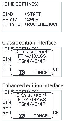
- Select BIND SETTINGS and press Scroll Wheel to enter.
- Select RF STD and press Scroll Wheel, then set it to 1WAY or 2WAY using Scroll Wheel.
- Select RF TYPE and press Scroll Wheel, then set an appropriate item. Press EXIT to save and exit.
6.5.2RX SET - PORT PROTOCOL
Set the type of output signal of the receiver interface. The interface shown on the left side can be set, and on the right side, the protocols that can be set.
For enhanced edition receiver: When no receiver is connected, 4 Newport interfaces are displayed by default for setting; when a receiver is connected, the Newport interfaces that can be set on this receiver are displayed, you can set the protocol to PWM, PPM, S.BUS, i-BUS-IN or i-BUS-OUT.
For classic edition receiver: When no receiver is connected, i-BUS and CH1 are displayed by default; when a receiver is connected, the interfaces that can be set are displayed.
Function settings:
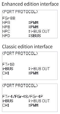
- Select PORT PROTOCOL and press Scroll Wheel to enter.
- Select the interface you want to set and press Scroll Wheel, then set an appropriate protocol using Scroll Wheel.
- Press EXIT to save and exit.
Notes:
- Neither classic edition receiver nor enhanced edition receiver supports i-BUS-IN setting in one-way communication.
- The signal types that can be selected once only in multiple for any Newport: PPM, S.BUS, i-BUS-IN and i-BUS-OUT. If it is selected for NPA, i-BUS-OUT cannot be selected again for NPD/NPC/NPB.
- If the interface protocol is set to i-BUS-IN, it can be used to connect the i-BUS sensors.
- If the interface protocol is set to i-BUS-OUT, it supports i-BUS/S.BUS signal output, the FS-CEV04 serial BUS receiver can be connected as well.
- The Newport interface of the enhanced receiver is abbreviated NPA, NPB, NPC, and NPD. And the enhanced receiver supports up to 4 Newport interfaces.
6.5.3RX SET - FAILSAFE
For failsafe, the transmitter provides the following three settings:
- To disable the signal output of i-BUS-out and PPM protocol interfaces in case of out-of-control, i.e., no output for i-BUS-out & PPM interfaces in case of out-of-control.
- Set all channels. That is, all channels are set to the same value. It can be set one of NONE, HOLD, or FIXED VALUE.
- Set failsafe values channel by channel to one of NONE, FIXED VALUE or HOLD.
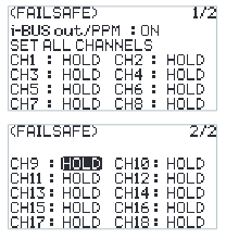
| I-BUS out/PPM | This function is for i-BUS and PPM signals. After the i-BUS-out/PPM function is enabled, regardless of the setting of the failsafe, these two types of failsafe signals are always no output. If the function is disabled, after out-of-control, you can set by channel to a fixed value or keep the last output value. By default, this function is enabled. |
| SET ALL CHANNELS | All channels are set to the same value. It can be set one of NONE, HOLD, or FIXED VALUE. NONE means that there is no output in case of out-of-control. HOLD means the last channel value is kept in case of out-of-control. FIXED VALUE means that you can set the failsafe output value by moving the control, then the value set will output in case of out-of-control. |
| CH1~CH18 | To set the output signal of CH1 to CH18, it can be set to None, Hold, or Fixed value. |
Function settings:
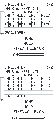
- Select FAILSAFE and press Scroll Wheel to enter.
- Select the item you want to set and press Scroll Wheel.
- Then set an appropriate value using Scroll Wheel. Press EXIT to save and exit.
6.5.4RX SET - PWM FREQUENCY
The receiver's output frequency of PWM signals can be regulated. Theoretically, the higher the frequency, the faster the signal is refreshed, and the faster the servo responds to the signal change. However, some servos may not support PWM signals with excessively high frequency. You may need to take into account the servo's performance when doing such settings.
The interface of this function may vary with bind modes. For enhanced edition receivers, the PWM frequency of each channel can be set separately, and the options include ANALOG (50Hz), DIGITAL (333 Hz), SR (833 Hz), SFR (1000 Hz) and CUSTOM.
If a classic receiver is bound, all channels are set together, and the options include ANALOG (50Hz), DIGITAL (333 Hz) and CUSTOM. It cannot be set to SR (833 Hz) and SFR (1000 Hz).
| SET ALL CHANNELS | All channels are set to the same frequency value. |
| CH1~CH18 | To set the PWM frequency of CH1 to CH18 separately. |
Function settings:
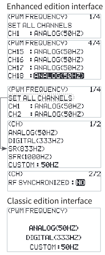
- Select PWM FREQUENCY and press Scroll Wheel to enter.
- Select the item you want to set and press Scroll Wheel.
- Then select/set an appropriate value using Scroll Wheel. Press EXIT to save and exit.
6.5.5RX SET - SIGNAL STRENGTH
Through this function, you can select a channel to output the signal strength value of the receiver. After the function is enabled, the selected channel does not perform the output of transmitter's corresponding channel function, but outputs the receiver's signal strength value. When the function enables, the CH14 is the default channel. This function is necessary for users who use FPV glasses in the operations of traversers. We recommend you to select the CH14 or any auxiliary channel. You can make corresponding adaptations in the flight control settings to view the signal strength information on FPV glasses.
Function settings:
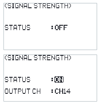
- Select SIGNAL STRENGTH and press Scroll Wheel to enter.
- Select STATUS and press Scroll Wheel.
- Select OUTPUT CH using Scroll Wheel and set an appropriate channel as you desired. Press EXIT to save and exit.
6.5.6RX SET - SENSOR
Except the functions described in 6.4.3 RX SET - SENSOR section, it can also check the temperature and voltage information of external RF module FRM303, and set whether to display it on the home page and alarm function as well.
| RF TEMP (temperature) | To display the temperature of the FRM303 RF module. |
| RF VOL (voltage) | To display the voltage of the FRM303 RF module. |
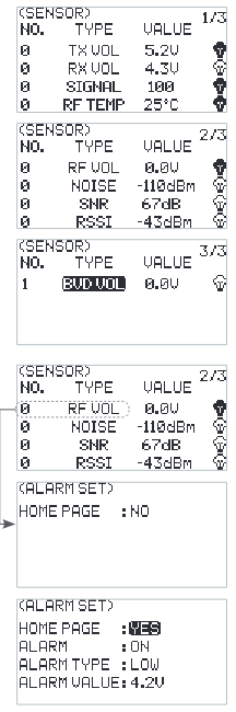
See 6.4.3 RX SET - SENSOR section for function settings.
Note: If the i-BUS sensor is connected to an enhanced edition receiver, then set the interface protocol of the Newport to i-BUS IN.
6.5.7RX SET - GPS SETTING
Please refer to 6.4.5 RX SET - GPS SETTING for this function.
6.5.8RX SET - RF SETTINGS
Except the functions described in 6.4.8 RX SET - RF SETTINGS section, it can also enable or disable the buzzer alarm function, and you can set an appropriate power if the FRM303 RF module supports power regulation by POWER SETTING function. In addition, you can view the related information about the RF module as well.
POWER SETTING (power regulation)
Set the power of FRM303 RF module, the options include 25mW, 100mW, 500mW, 1W, or 2W.
Note that the power supply mode affects the power output. When the RF module is supplied externally, the maximum power output is 2W; the maximum output power is 25mW for USB power supply; and the maximum output power is 500mW for internal power supply.
Function settings:
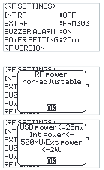
- Select POWER SETTING, a prompt screen comes along with it to show the output power information. Then press OK.
- Set an appropriate power as you desired. Press EXIT to save and exit.
RF VERSION
To view information about the RF module, such as version, model, ID, and whether the RF power can be regulated or not.
Function settings:
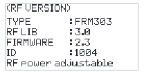
Select RF VERSION and press Scroll Wheel to view the related information. Press EXIT to exit.
6.5.9RX SET - ABOUT RECEIVER
Display information about the receiver bound, such as receiver model, version, and ID.
Function settings:
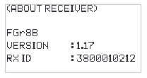
Select ABOUT RECEIVER and press Scroll Wheel to view the related information. Press EXIT to exit.
7FS-SR8 Function Instructions
FS-SR8 based on ANT protocol is an 8-channel receiver with two external antennas and bidirectional transmission. It has a compact design. The design of the receiver is easy to install, and it adapts to a variety of models.
Note: See 2.2 Receiver Overview for interface introduction details.
7.1Attentions
- Make sure the product is installed and calibrated correctly, failure to do so may result in serious injury.
- Normally, you must power on the transmitter and then receiver, and power off the receiver and then the transmitter.
- Unreasonable setting of the Failsafe may cause accidents.
- Make sure the receiver is mounted away from motors, electronic speed controllers or any device that emits excessive electrical noise.
- Keep the receiver's antenna at least 1cm away from conductive materials such as carbon or metal.
- Do not power on the receiver during the setup process to prevent loss of control.
7.2Binding
If you need to re-bind the receiver, please refer to 4.3 Binding for the steps.
Note: Put the transmitter in bind mode first, and then put the receiver in bind mode.
7.3RSSI
The RSSI data is output via channel 14 to flight control in the manner of SERVO/S.BUS signal. When the signal strength is 0, the corresponding channel output value is 1000, and when the signal strength is 100, the corresponding channel output value is 2000.
7.4Updating the Firmware of the Receiver
The firmware of this receiver is updated through the FlyskyAssistant (only version 3.0 or above is supported; the FlyskyAssistant is available on the Flysky official website).
This receiver can be updated via the following two ways:
- After the binding between the transmitter and the receiver (the LED of the receiver is solid on), connect the transmitter to the computer, then open the FlyskyAssistant on the computer to update the firmware.
- Connect the transmitter to the computer. Then put the receiver to enter the forced update mode by referring to the following three ways (the LED of the receiver works in three-flash-one-off mode repeatedly). Afterwards, open the FlyskyAssistant on the computer to update the firmware.
- Power on the receiver while pressing and holding the BIND button for more than ten seconds, until the LED of the receiver operates in three-flash-one-off manner repeatedly, then release the BIND button.
- Power on the receiver first, then press and hold the BIND button for more than ten seconds, when the LED of the receiver operates in three-flash-one-off manner repeatedly, then release the BIND button.
- Connect the signal pin of the BIND interface to the signal pin of the SENS interface, then power on the receiver.
7.5Failsafe of the Receiver
This receiver supports two failsafe modes: ON and OFF. You can set it at transmitter side. Please refer to Failsafe in the previous description.
8DIY Customization
The system can be reconfigured to change stick placement, mount mobile stand, RF adapter or SMA antenna.
8.1Throttle Metal Bracket Installation
FS-ST8 transmitter has two sticks in the factory settings, and one is the self-centering stick. To use the non self-centering stick, please follow the steps below to replace the self-centering stick with the non self-centering stick. The throttle plate includes two types: setback sense throttle plate and non setback sense throttle plate (the installation steps are the same).
- This operation is only for the self-centering stick. It is forbidden to disassemble the non self-centering stick.
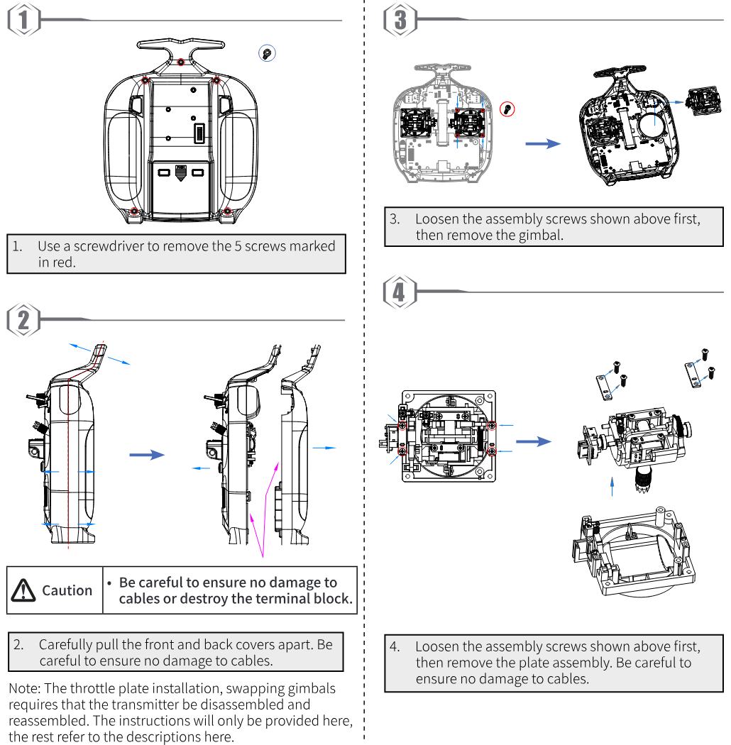
- Use a screwdriver to remove the 5 screws marked in red.
- Carefully pull the front and back covers apart. Be careful to ensure no damage to cables.
- Loosen the assembly screws shown above first, then remove the gimbal.
- Loosen the assembly screws shown above first, then remove the plate assembly. Be careful to ensure no damage to cables.
- Be careful to ensure no damage to cables or destroy the terminal block.
Note: The throttle plate installation and swapping gimbals require that the transmitter be disassembled and reassembled. The instructions will only be provided here; the rest refer to the descriptions here.
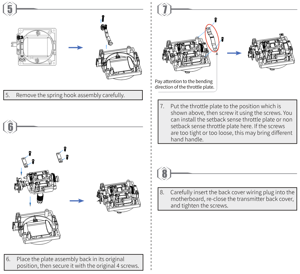
- Remove the spring hook assembly carefully.
- Place the plate assembly back in its original position, then secure it with the original 4 screws.
- Put the throttle plate to the position which is shown above, then screw it using the screws. Pay attention to the bending direction of the throttle plate. You can install the setback sense throttle plate or non setback sense throttle plate here. If the screws are too tight or too loose, this may bring different hand feel.
- Carefully insert the back cover wiring plug into the motherboard, re-close the transmitter back cover, and tighten the screws.
8.2Throttle Spring Installation
The following instructions explain how to change the non self-centering to self-centering.
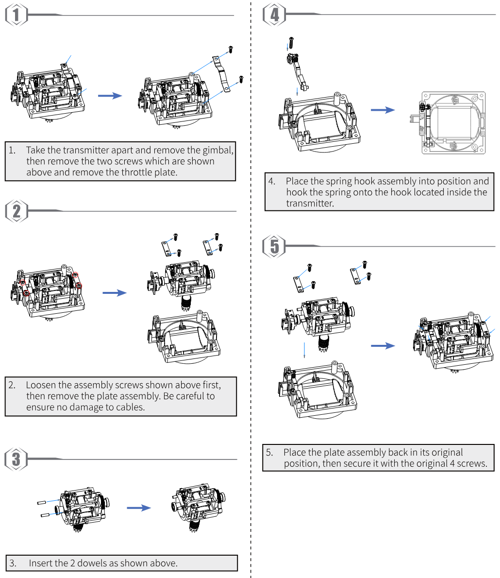
- Take the transmitter apart and remove the gimbal, then remove the two screws which are shown above and remove the throttle plate.
- Loosen the assembly screws shown above first, then remove the plate assembly. Be careful to ensure no damage to cables.
- Insert the 2 dowels as shown above.
- Place the spring hook assembly into position and hook the spring onto the hook located inside the transmitter.
- Place the plate assembly back in its original position, then secure it with the original 4 screws.
8.3Swapping Gimbals
When changing between modes 2/4 (M2/M4) and modes 1/3 (M1/M3), you will need to switch the gimbals around so that the throttle gimbal is on the correct side.
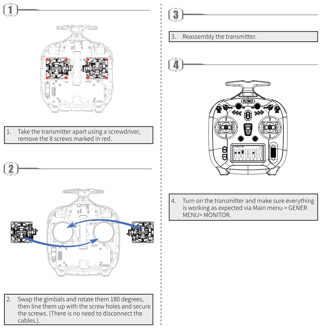
- Take the transmitter apart using a screwdriver, remove the 8 screws marked in red.
- Swap the gimbals and rotate them 180 degrees, then line them up with the screw holes and secure the screws. (There is no need to disconnect the cables.)
- Reassemble the transmitter.
- Turn on the transmitter and make sure everything is working as expected via Main menu > GENER MENU > MONITOR.
8.4Device Holder Installation
Mobile devices, such as mobile phone, can be used in real time to receive information from an aircraft; it may be fitted into the mobile device bracket for your convenience.
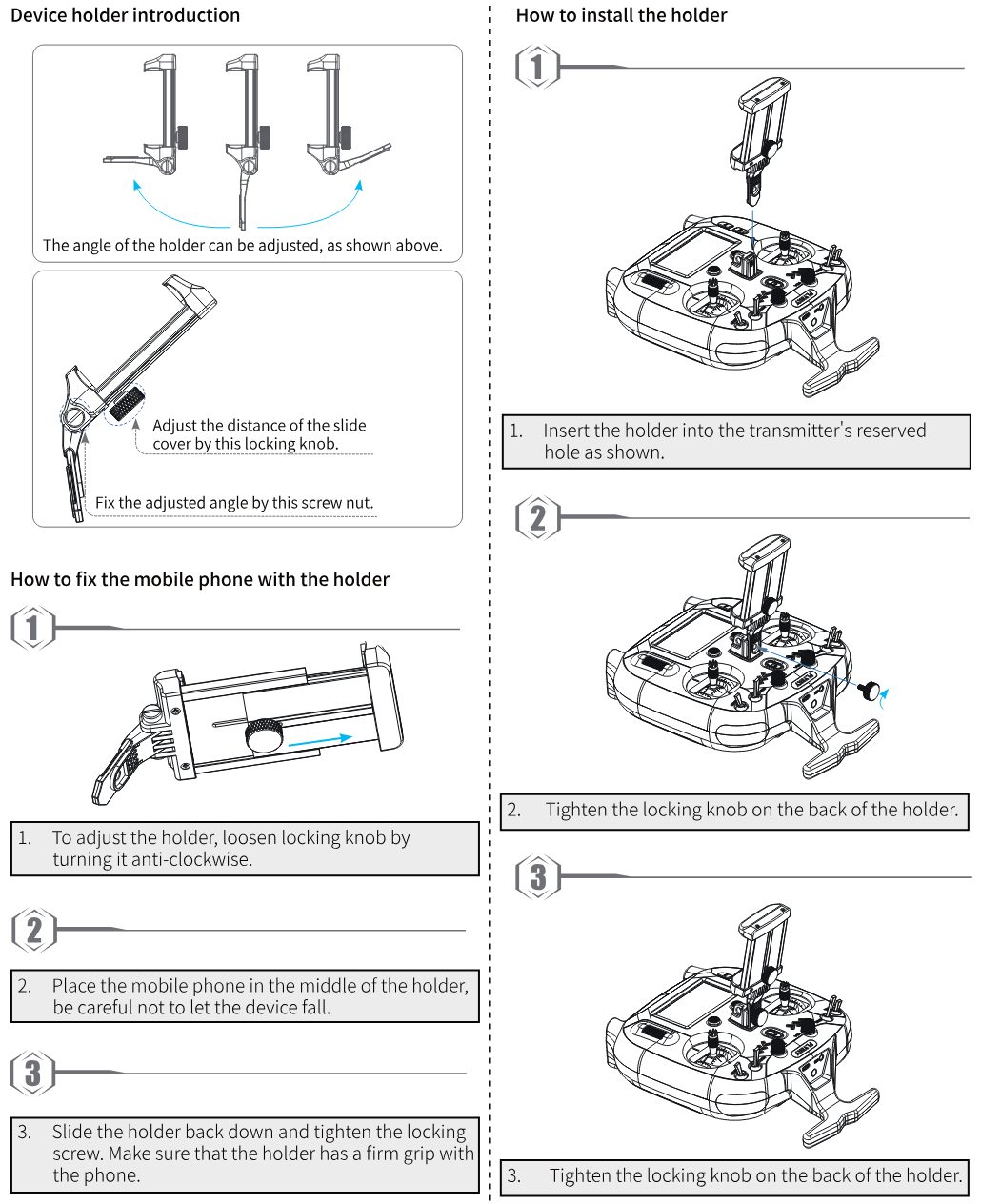
Device holder introduction: The angle of the holder can be adjusted. Adjust the distance of the slide cover by the locking knob. Fix the adjusted angle by the screw nut.
How to fix the mobile phone with the holder:
- To adjust the holder, loosen the locking knob by turning it anti-clockwise.
- Place the mobile phone in the middle of the holder, be careful not to let the device fall.
- Slide the holder back down and tighten the locking screw. Make sure that the holder has a firm grip with the phone.
How to install the holder:
- Insert the holder into the transmitter's reserved hole as shown.
- Tighten the locking knob on the back of the holder.
- Tighten the locking knob on the back of the holder.
8.5Stealth I/O RF Module Adapter Installation
If you have purchased the RF module adapter, fix it on the transmitter by following the steps below:
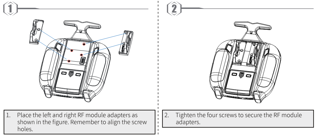
- Place the left and right RF module adapters as shown in the figure. Remember to align the screw holes.
- Tighten the four screws to secure the RF module adapters.
Note: The transmitter Stealth I/O RF module interface is designed without power supply. Stealth I/O RF module interface pins are defined as shown in the figure below. If you connect the RF module externally through the RF module adapter, you need to supply power to the RF module separately.
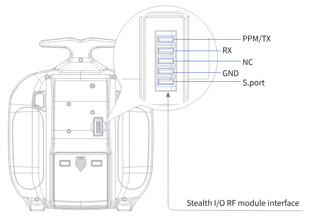
8.6Antenna Assembly Installation
If you have purchased the 2.4G antenna assembly inner-screw-inner-hole, the installation procedure is described below.
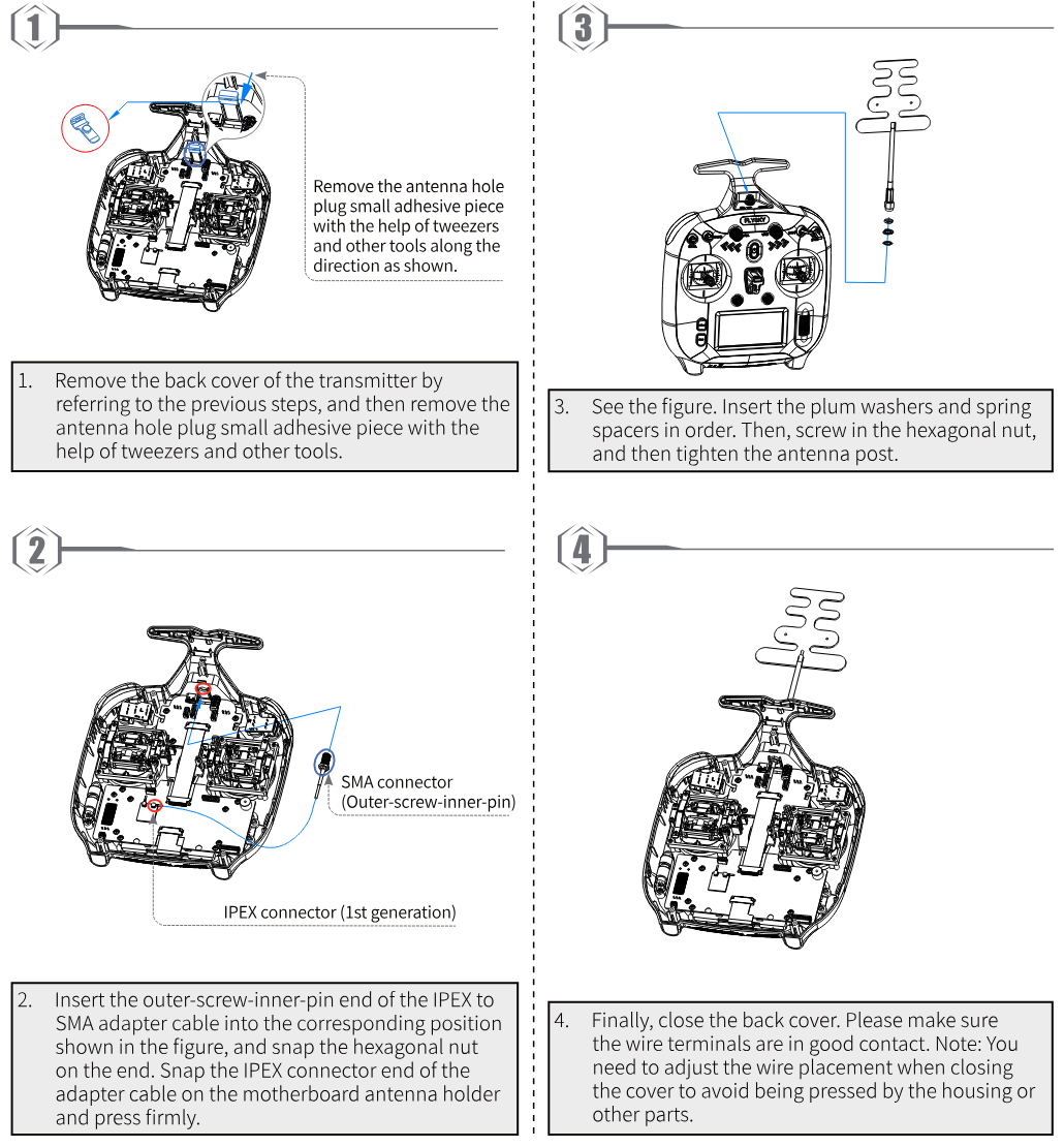
- Remove the back cover of the transmitter by referring to the previous steps, and then remove the antenna hole plug small adhesive piece with the help of tweezers and other tools along the direction as shown.
- Insert the outer-screw-inner-pin end of the IPEX to SMA adapter cable into the corresponding position shown in the figure, and snap the hexagonal nut on the end. Snap the IPEX connector end of the adapter cable on the motherboard antenna holder and press firmly.
- See the figure. Insert the plum washers and spring spacers in order. Then, screw in the hexagonal nut, and then tighten the antenna post.
- Finally, close the back cover. Please make sure the wire terminals are in good contact. Note: You need to adjust the wire placement when closing the cover to avoid being pressed by the housing or other parts.
8.7Gimbal Replacement Instruction
The factory-adapted gimbal assembly of the transmitter is the potentiometer version. If you want to change it to FlySky's hall gimbal, then follow the steps below to replace the gimbal.
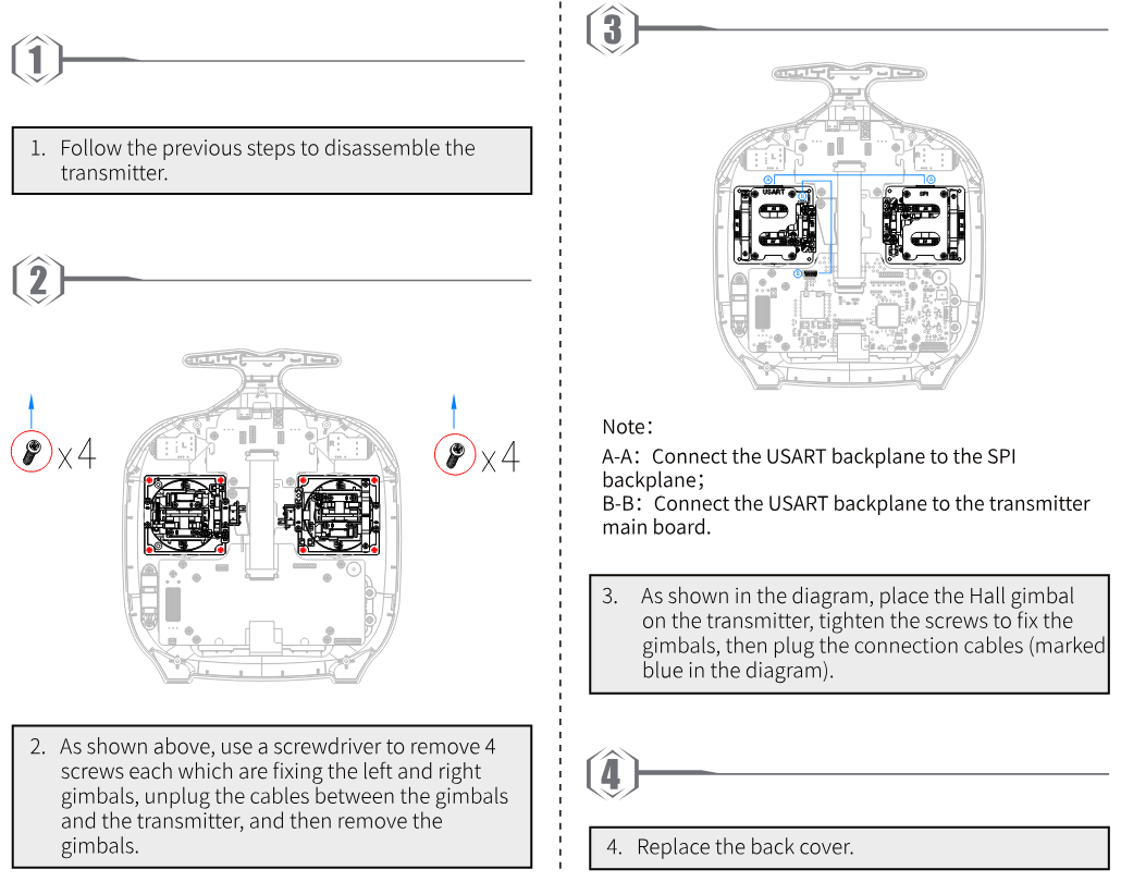
- Follow the previous steps to disassemble the transmitter.
- As shown above, use a screwdriver to remove 4 screws each which are fixing the left and right gimbals, unplug the cables between the gimbals and the transmitter, and then remove the gimbals.
- As shown in the diagram, place the Hall gimbal on the transmitter, tighten the screws to fix the gimbals, then plug the connection cables (marked blue in the diagram). Note: A-A: Connect the USART backplane to the SPI backplane; B-B: Connect the USART backplane to the transmitter main board.
- Replace the back cover.
9Product Specifications
This section contains FS-ST8 transmitter and FS-SR8 receiver specifications.
9.1Transmitter Specifications (FS-ST8)
| Product Model | FS-ST8 |
| Number of Channels | 8-12 |
| Compatible Receiver | FS-SR8 (adapts receiver with ANT protocol) |
| Compatible RC Models | Fixed-wing aircraft, helicopters, gliders, delta-wing airplanes, multicopters, racing drones, engineering vehicles, robots, cars or boats, etc. |
| RF | 2.4GHz ISM |
| Maximum Power | < 20dBm (e.i.r.p.) (EU) |
| RF Protocol | ANT |
| Distance | More than 1000m (air distance without interference) |
| Resolution | 4096 |
| Input Power | 1.5V AA × 4 / 2S LiPo (JST) |
| Charging Jack | None |
| Data Connector | USB Type-C, 3.5mm audio jack |
| Low Voltage Warning | AA battery: < 4.2V / LiPo battery: < 7.2V |
| Antenna | Built-in double antennas |
| Display | 128 × 64 LCD (black and white dot matrix screen) |
| Temperature Range | -10℃ ~ +60℃ |
| Humidity Range | 20% ~ 95% |
| Firmware Update | Supported |
| Color | Black |
| Dimensions | 176 × 210.9 × 82.5mm |
| Weight | 420g |
| Certifications | CE, FCC ID: N4ZST800 |
9.2Receiver Specifications (FS-SR8)
| Product Model | FS-SR8 |
| Compatible Transmitters | FS-ST8 (adapts transmitter with ANT protocol) |
| Compatible RC Models | Fixed-wing aircraft, helicopters, gliders, delta-wing airplanes, multicopters, racing drones, engineering vehicles, robots, cars or boats, etc. |
| Number of PWM Channels | 8 |
| RF | 2.4GHz ISM |
| RF Protocol | ANT |
| Resolution | 4096 |
| Distance | More than 1000m (air distance without interference) |
| Antenna | Two antennas |
| Operating Voltage | 3.5~9V/DC |
| Data Output | PWM/PPM/i-BUS/S.BUS |
| Firmware Update | Supported |
| Temperature Range | -10℃ ~ +60℃ |
| Humidity Range | 20% ~ 95% |
| Weight | 10g |
| Dimensions | 44.8 × 26.6 × 11.3mm |
| Certifications | CE, FCC ID: 2A2UNSR800 |
10Package Contents
This section contains packing list information. Different versions have different configurations, please consult your dealer for details.
For Standard Edition
| Number | Name | Quantity | Remark |
|---|---|---|---|
| 1 | FS-ST8 Transmitter | 1 | |
| 2 | FS-SR8 Receiver | 1 | |
| 3 | Quick Start Guide | 1 |
For Upgraded Edition
| Number | Name | Quantity | Remark |
|---|---|---|---|
| 1 | FS-ST8 Transmitter | 1 | |
| 2 | FS-SR8 Receiver | 1 | |
| 3 | Quick Start Guide | 1 | |
| 4 | Throttle Self-centering Modification Parts | 1 | |
| 5 | FGPZ05 RF Module Adapter | 1 | |
| 6 | Throttle Bracket Parts | 1 | |
| 7 | Device Holder | 1 | Optional |
| 8 | External FS-FRA01 2.4G Antenna Modification Parts | 1 | Optional |
| 9 | FGPZ03 RF Module Adapter | 1 | Optional |
| 10 | FGPZ05 RF Module Adapter | 1 | Optional |
11Certifications
11.1DoC Declaration
Hereby, [ShenZhen FLYSKY Technology Co., Ltd.] declares that the Radio Equipment [FS-ST8] is in compliance with RED 2014/53/EU.
The full text of the EU DoC is available at the following internet address: www.flyskytech.com/info_detail/10.html.
11.2CE Warning
The CE warns that the installation of the antenna used in this transmitter must be kept in distance from all the personnel and shall not be used or used with any other transmitter. The end user and the installer must provide antenna installation instructions and transmitter operating conditions to meet the requirements for RF exposure compliance.
SAR: The maximum SAR value is 2.57W/kg when the equipment is used 5mm close to the user.
11.3FCC Statement
This equipment has been tested and found to comply with the limits for a Class B digital device pursuant to part 15 of the FCC rules. These limits are designed to provide reasonable protection against harmful interference in a residential installation. This equipment generates, uses and can radiate radio frequency energy and, if not installed and used in accordance with the instructions, may cause harmful interference to radio communications. However, there is no guarantee that interference will not occur in a particular installation. If this equipment does cause harmful interference to radio or television reception, which can be determined by turning the equipment off and on, the user is encouraged to try to correct the interference by one or more of the following measures:
- Reorient or relocate the receiving antenna.
- Increase the separation between the equipment and receiver.
- Connect the equipment into an outlet on a circuit different from that to which the receiver is connected.
- Consult the dealer or an experienced radio/TV technician for help.
To assure continued compliance, any changes or modifications not expressly approved by the party responsible for compliance could void the user's authority to operate this equipment.
This equipment complies with Part 15 of the FCC Rules. Operation is subject to the following two conditions: (1) This device may not cause harmful interference, and (2) this device must accept any interference received, including interference that may cause undesired operation.
Caution! The manufacturer is not responsible for any radio or TV interference caused by unauthorized modifications to this equipment. Such modifications could void the user authority to operate the equipment.
12Environmentally Friendly Disposal
Old electrical appliances must not be disposed of together with the residual waste, but have to be disposed of separately. The disposal at the communal collecting point via private persons is for free. The owner of old appliances is responsible to bring the appliances to these collecting points or to similar collection points. With this little personal effort, you contribute to recycle valuable raw materials and the treatment of toxic substances.
- RISK OF EXPLOSION IF BATTERY IS REPLACED BY AN INCORRECT TYPE. DISPOSE OF USED BATTERIES ACCORDING TO THE INSTRUCTIONS.
- Replacement of a battery with an incorrect type can defeat a safeguard (for example, in the case of some lithium battery types).
- Disposal of a battery into fire or a hot oven, or mechanically crushing or cutting of a battery, can result in an explosion.
- Leaving a battery in an extremely high temperature surrounding environment can result in an explosion or the leakage of flammable liquid or gas.
- A battery subjected to extremely low air pressure may result in an explosion or the leakage of flammable liquid or gas.
Figures and illustrations in this manual are provided for reference only and may differ from actual product appearance. Product design and specifications may be changed without notice.