
1Safety
1.1Safety Symbols
Pay close attention to the following symbols and their meanings. Failure to follow these warnings could cause damage, injury or death.
| Danger | Not following these instructions may lead to serious injuries or death. |
| Warning | Not following these instructions may lead to major injuries. |
| Attention | Not following these instructions may lead to minor injuries. |
1.2Safety Guide
Prohibited:
- Do not use the product at night or in bad weather like rain or thunderstorm. It can cause erratic operation or loss of control.
- Do not use the product when visibility is limited.
- Do not use the product on rain or snow days. Any exposure to moisture (water or snow) may cause erratic operation or loss of control.
- Interference may cause loss of control. To ensure the safety of you and others, do not operate in the following places: near any site where other radio control activity may occur; near power lines or communication broadcasting antennas; near people or roads; on any body of water when passenger boats are present.
- Do not use this product when you are tired, uncomfortable, or under the influence of alcohol or drugs. Doing so may cause serious injury to yourself or others.
- The 2.4GHz radio band is limited to line of sight. Always keep your model in sight as a large object can block the RF signal and lead to loss of control.
- Do not touch any part of the model that may generate heat during operation, or immediately after use. The engine, motor or speed control may be very hot and can cause serious burns.
Mandatory:
- Misuse of this product may lead to serious injury or death. To ensure the safety of you and your equipment, read this manual and follow the instructions.
- Make sure the product is properly installed in your model. Failure to do so may result in serious injury.
- Make sure to disconnect the receiver battery before turning off the transmitter. Failure to do so may lead to unintended operation and cause an accident.
- Ensure that all motors operate in the correct direction. If not, adjust the direction first.
- Make sure the model stays within the system's maximum range to prevent loss of control.
2Introduction
This product uses the 2.4 GHz ANT (Ant protocol) enhanced automatic frequency hopping digital system, consisting of the FS-ST16 transmitter and the FS-SR8 receiver. It has an output of 16 channels. And there is a variety of built-in models that you can set as desired. It adapts to fixed-wing aircraft, helicopters, gliders, multicopters, robots, boats or cars.
2.1Transmitter Overview
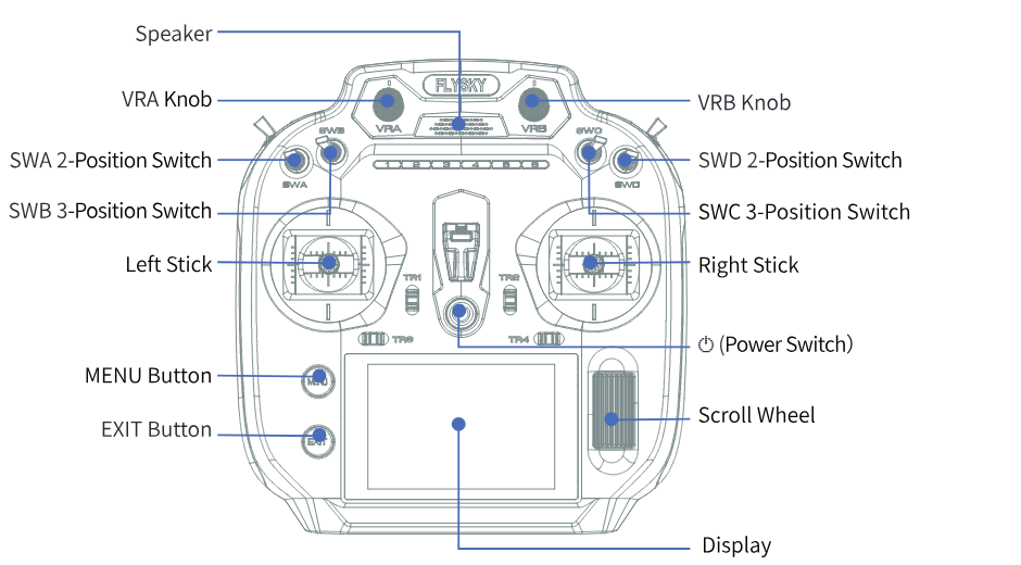
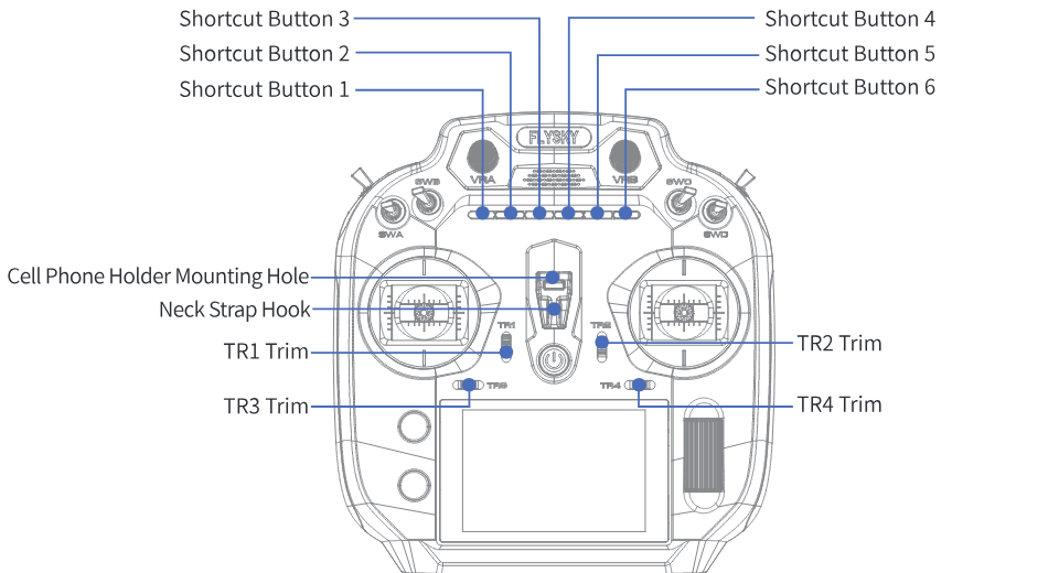
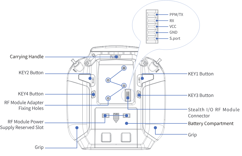
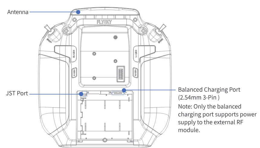
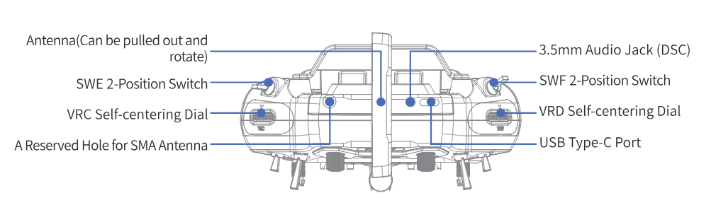
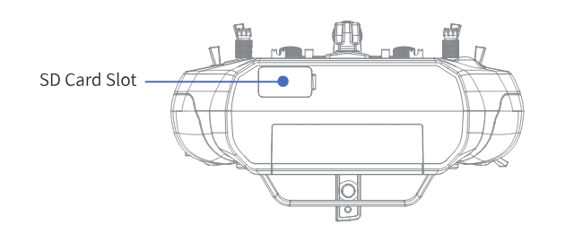
2.1.1Control (MENU Button/EXIT Button/Scroll Wheel)
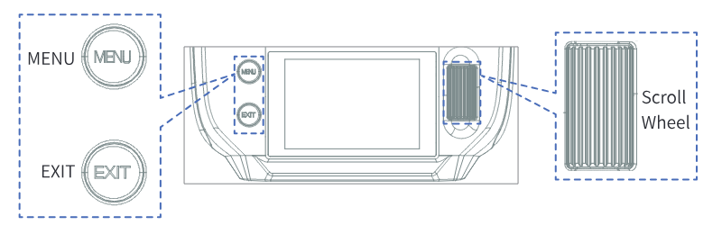
The functions of the MENU button, EXIT button, and scroll wheel are described below.
MENU button
- On the Home interface, short press the MENU button to enter the Main Menu interface.
- When not on the Home interface, short press the MENU button to return to Home, but it cannot return to Home during a pop-up or firmware update.
EXIT button
- On the Home interface, short press the EXIT button to enter the Home 2 interface.
- On the Home interface, long press the EXIT button for 2 s to lock the screen; long press it again to unlock the screen.
- When not on the Home interface, short press the EXIT button to return to the previous interface or exit the editing mode.
Scroll wheel
- On the Home, Home 2, main menu or functional interface, scroll the wheel to select the function item, and short press the scroll wheel to enter the function item.
- In the function item settings state, scroll the wheel to adjust the parameter; quickly scroll the wheel to adjust rapidly. Short press the scroll wheel to save and exit.
- In the function interface, long press the scroll wheel for 2 s to reset all the data on the current page to default values.
- In the function settings state, if there are only two parameters, short press the scroll wheel to switch between them.
2.2Receiver Overview (FS-SR8)
![The FS-SR8 receiver from the side and above with its numbered parts [1] to [18]](/manuals/fs-st16/receiver.png)
| [1]–[8] | CH1–CH8 |
| [9] | BIND connector |
| [10] | BVD/VCC (battery voltage detection / power supply connector) |
| [11] | SENS |
| [12] | SERVO/S.BUS |
| [13] | − (power cathode) |
| [14] | + (power anode) |
| [15] | S (signal pin) |
| [16] | LED |
| [17] | Antenna |
| [18] | Bind button |
2.2.1Receiver LED
The LED status indicates the power supply state of the receiver and its working state.
- Off: The receiver is not powered on.
- Solid on: The receiver works normally.
- Fast flashing: The receiver is in binding mode.
- Slow flashing: The bound transmitter is powered off, or the receiver has not been bound with a transmitter, or the receiver does not receive any signal.
- Three-flash-one-off: The receiver is in forced update mode.
- Flash once, on once, off once: The receiver has been set as a PWM converter.
2.2.2Connector
All channel connectors are 2.54 mm 3-pin standard pins, and the connectors are used to connect the receiver to the various components of the model.
Note: When using, please pay attention to the indicator marks on the receiver to ensure correct operation. Some marks may be located on the side of the receiver. Please operate according to the direction indicated by the marks to avoid misuse or damage to the equipment.
3Getting Started
Before operation, install the battery and connect the system as instructed below.
3.1Transmitter Battery Installation
- Only use the included batteries.
- Do not open, disassemble, or attempt to repair the battery.
- Do not crush/puncture the battery, or short the external contacts.
- Do not expose to excessive heat or liquids.
- Do not drop the battery or expose it to strong shocks or vibrations.
- Always store the battery in a cool, dry place.
- Do not use the battery if damaged.
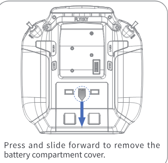
Installing the 18650 battery
- Open the battery compartment cover as shown.
- Insert 2 batteries into the compartment. Make sure that the batteries are set according to the polarities marked on the battery compartment.
- Close the battery compartment cover.
Installing the LiPo battery
The transmitter supports LiPo batteries which are equipped with either a JST connector or a balanced charging connector on the battery wiring. Follow the steps below to install the LiPo batteries:
- Open the battery compartment cover.
- Use a Phillips screwdriver to remove the two screws that secure the 18650 battery holder, and then remove the battery holder.
- Insert 2S LiPo batteries into the compartment.
- Plug the battery wiring of the LiPo battery into the JST port or balanced charging port accordingly.
- Close the battery cover; pay attention to avoid pinching the battery wiring.
Notes:
- Only the balanced charging port can be used for charging.
- Once the transmitter has the battery installed, you can use a USB Type-C cable to connect to the transmitter's USB Type-C port for power supply.
- Only the balanced charging port supports power supply to the external RF module.
Adjust the antenna
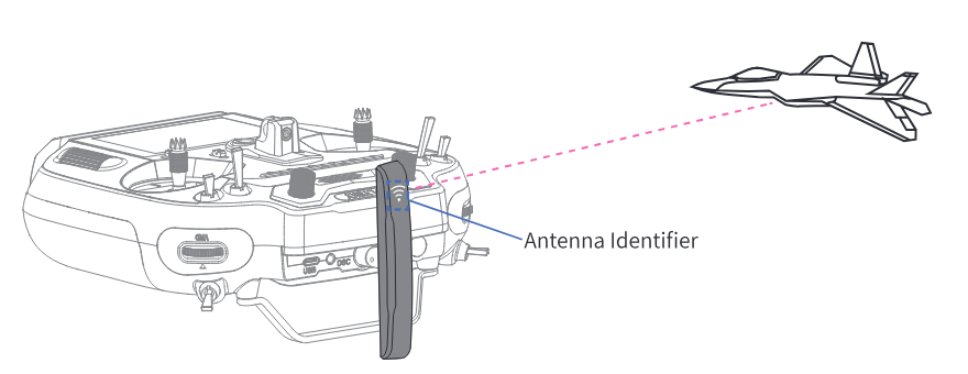
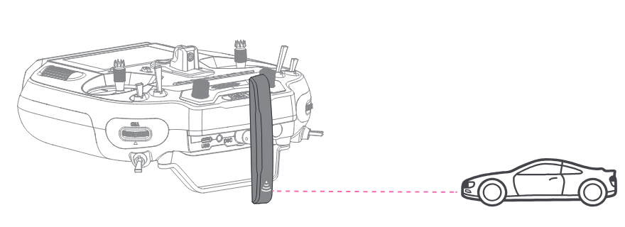
Pull out the transmitter antenna and rotate it to the appropriate position, as different antenna positions will receive varying signal strengths. Based on the relative position of the transmitter and the model, adjust the direction of the transmitter's external antenna and align the antenna identifier towards the model to ensure the best signal quality between the transmitter and the model.
The suggested antenna angles for operating a model with the transmitter are shown in the figures below.
4Operation Instructions
After setting up, follow the instructions below to operate the system.
4.1Powering On

Follow the steps below to turn on the transmitter:
- Check to make sure that the batteries are fully charged and installed correctly.
- Long press the power switch, and follow the prompts on the screen to successfully power on.
- If the built-in RF module is not detected or needs to be updated, the system will prompt a pop-up window. Please follow the instructions in the pop-up window to proceed.
- Whether the switch is in the safe position (if the control background is highlighted in red, it indicates that the position needs adjustment). Please check the position of the control according to the prompts and follow the prompts to adjust it to the correct position.
- The system will pop up a window prompting whether the failsafe is set for the current model. To turn off the failsafe prompt, select No or turn off the Failsafe Prompt through System.
- If the system is powered on using the USB Type-C port without a battery installed, a pop-up window will appear: "Please use after installing the battery!"
- Operate with caution in order to avoid damage or injury.
- Make sure that the throttle is at its lowest position and the switches are set to their up position.
4.2Binding
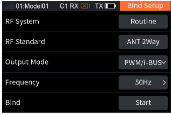
The transmitter and the receiver have been pre-bound before delivery. If you need to use other receivers, follow the steps below to bind the transmitter and the receiver. The transmitter supports both ANT 2 Way and ANT 1 Way binding, and ANT 2 Way binding is the default setting. The transmitter will display the information returned by the receiver after the ANT 2 Way binding is completed. Before binding, it is necessary to set RF System, RF Standard, Output Mode, and Frequency according to the actual application scenario.
- [RF System]: Two modes are available: Routine and Fast. In Routine mode, it presents strong anti-interference performance against other devices, while Fast mode provides better coexistence with lower latency and power consumption.
- [RF Standard]: To select the RF protocol, either ANT 2 Way or ANT 1 Way.
- [Output Mode]: Two combined output options are available, including four output modes, namely PWM/S.BUS, PPM/i-BUS, PWM/i-BUS and PPM/S.BUS. Choose according to your needs. Using the FS-ST16 transmitter and FS-SR8 receiver for binding as an example: when the [Output Mode] is set to PWM/S.BUS, connectors such as CH1 output PWM signals, and the SERVO connector outputs S.BUS signals. When set to PPM/i-BUS, the CH1 connector outputs PPM signals, other channel connectors have no output, and the SERVO connector outputs i-BUS signals. When set to PWM/i-BUS, connectors such as CH1 output PWM signals, and the SERVO connector outputs i-BUS signals. When set to PPM/S.BUS, the CH1 connector outputs PPM signals, other channel connectors have no output, and the SERVO connector outputs S.BUS signals. Note: Regardless of which type the receiver's [Output Mode] is set to, the SENS connector will output the i-BUS-in signal.
- [Frequency]: Set the frequency of the channels. Options include Digital Servo, Analog Servo, and Other.
After the above settings, complete the ANT 2 Way binding following the steps below:
- Select Start, and short press the scroll wheel; the transmitter will enter the binding state.
- Press and hold the BIND button of the receiver while powering on the receiver; the LED of the receiver should be flashing, indicating that the receiver is in bind mode. For other binding ways, please refer to the FS-SR8 receiver manual.
- When the receiver LED is solid on, it indicates successful binding.
- Check whether the transmitter and receiver are operating properly. For re-binding, please repeat the above steps.
Note: If the transmitter that has its RF standard set to ANT 1 Way enters bind mode, put the transmitter out of the binding state when the status of the receiver LED changes to slow flash; at the same time, the receiver LED is solid on, indicating that the binding is completed.
- This binding procedure applies to the FS-ST16 transmitter and FS-SR8 receiver; different receivers may enter the forced update in different ways, please go to the FLYSKY website to query the instructions of the relevant receiver.
- The products are subject to constant update. Please enter the FLYSKY website for the latest transmitter and receiver compatibility form.
4.3LED
The transmitter LED includes the power indicator (located at the power button), the main ambient lights (located around the gimbal assemblies) and the secondary ambient lights (located at the shortcut buttons 1–6). The transmitter LED can be adjusted for color and brightness according to different scenarios and personal preferences. The specific reference for the transmitter LED is 14.1.9 Main light.
4.4Stick Cal
Use this function to correct the mechanical deviation of the controls (left/right stick, VRA and VRB knobs, VRC and VRD self-centering dials), for example deviation in the self-centering or maximum/minimum travel. By default, the calibration is finished. If you need to calibrate again, follow the steps below:
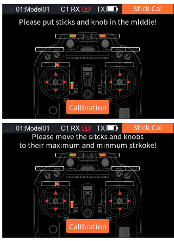
- Go to Home > Main Menu > RX Menu, and select Stick Cal, then short press the scroll wheel, select Yes on the pop-up interface, then short press the scroll wheel to enter the function interface.
- Move the controls to their center positions according to the prompt, and short press the scroll wheel.
- Move the controls to their max/min travels, and short press the wheel; the calibration interface is exited, indicating the calibration is successful. If the calibration fails, the system will pop up a prompt interface; scroll the wheel to select No and short press the scroll wheel to recalibrate, otherwise cancel the calibration.
4.5Powering Off
Follow the steps below to turn off the transmitter:
- Turn off the receiver first.
- Press and hold the power switch until the screen turns off, indicating that the transmitter is powered off.
- Make sure to disconnect the receiver power before turning off the transmitter. Failure to do so may lead to damage or serious injury.
5System Interface
This section provides an introduction to the system interface.
Home
In this interface, you can quickly access the Timer1, Timer2, Sensor Set, and Model Function settings interfaces by using the scroll wheel.
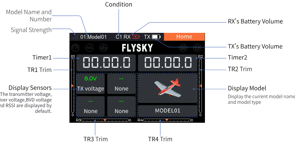
- Model name and number; signal strength; condition (C1); RX's battery volume; TX's battery volume.
- Timer1 / Timer2 and the trims TR1–TR4.
- Display sensors: the transmitter voltage, receiver voltage, BVD voltage and RSSI are displayed by default.
- Display model: displays the current model name and model type.
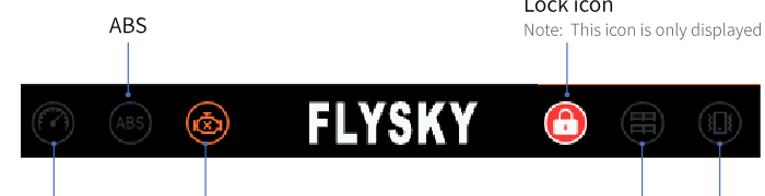
Function status display area
The function status bar displays the status of various functions. If the function shows in bright color, it is active; if it is light gray, it is inactive.
Home 2
You can customize the quick display function interface. The default display is the sensor settings interface.
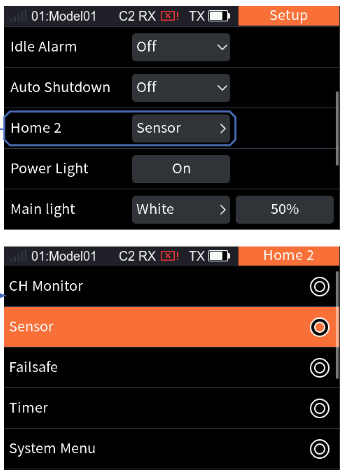
- Select [System Menu] > [Setup] > [Home 2].
- Short press the scroll wheel to enter the Home 2 settings interface, then scroll the wheel to select the function item, and short press the scroll wheel again to save the settings.
- Return to the Home page and short press the EXIT button to enter Home 2.
6Basic Menu
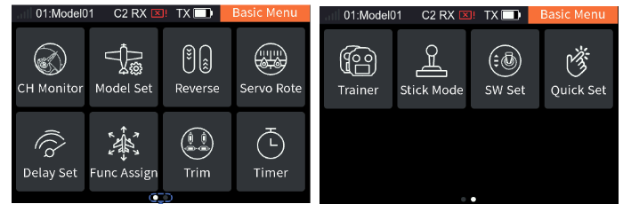
This section introduces the Basic Menu and related settings. Press the MENU button to enter the Main Menu, scroll the wheel to select [Basic Menu], and then press the wheel to enter the Basic Menu.
6.1CH Monitor
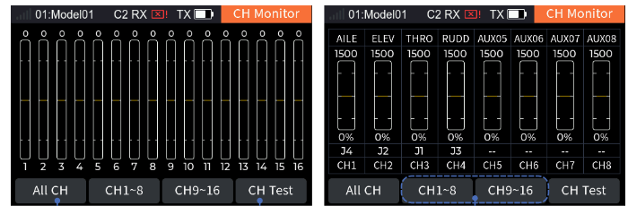
Used to display the real-time status of channels and to test servos.
6.1.1Display Servos
To display the real-time output value of each individual channel.
- Select [CH Monitor], then select the channel you need to monitor.
- Toggle the control assigned to the channel.
- Monitor the output value of the channel in the Display servos interface.
- Short press the EXIT button to return.
6.1.2CH Test
The servos can be tested. When it is turned on, the servos of all channels will move slowly and repeatedly. Please be cautious when the function is activated.
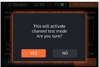
- Scroll the wheel to select [CH Test]; the system displays a pop-up window, choose [Yes] to enter the channel test mode. When test mode is active, all channels will slowly move through their entire range of motion.
- Short press the EXIT button to exit the interface and stop the test.
- Do not activate this function when the transmitter is connected to the model engine or the engine is started.
6.2Model Set
Used to set up functions related to the model.
6.2.1Model Select
Switch to the model to be used.
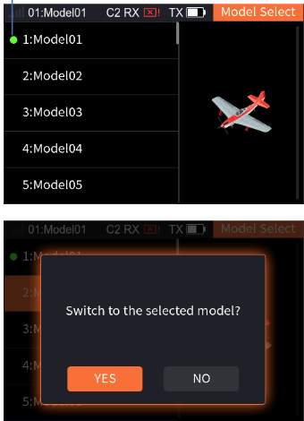
- Select [Model Select] to enter the Model Select setting interface.
- Scroll the wheel to select the desired model as needed, and when the system displays a pop-up window, choose [Yes] to confirm the switch.
6.2.2Model Name
Used to modify the name of the current model. Supports a maximum of 12 characters.
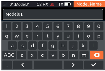
- Select [Model Name] to enter the soft keyboard interface.
- After setting an appropriate name, scroll the wheel to select the check mark, then short press the scroll wheel to return.
6.2.3Model Type
Set the model type and the model-related parameters and functions. For fixed-wing and glider models, you can set Wing layout, Tail layout, and Optional; for helicopter models, you can set Swash Plate and Optional; for car and robot models, you can set Move setup and Optional; for ship models, you can set Drive Struct and Optional.
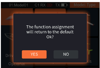
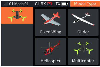
Take the airplane as an example; the setting steps are as follows. For the related settings of the glider, refer to the steps below.
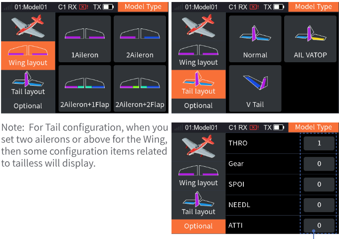
- Short press the scroll wheel to select [Model Type] and enter the function interface.
- Select [Wing layout] directly as the airplane is the default model, then select the appropriate wing configuration according to the actual model and short press the scroll wheel to save the settings. Afterwards, it goes to the next setting automatically.
- Select [Tail layout], then select the appropriate tail configuration according to the actual model and short press the scroll wheel to save the settings. Afterwards, it goes to the next setting automatically.
- Select [Optional], then select the appropriate functionality according to the actual model and save the settings.
Note: The optional function items vary with different model types. For example, for the airplane you can set the rudder wheel, gear and so on, but for the ship the wave and the grip can be set.
The following are the steps for setting up the helicopter's functions:
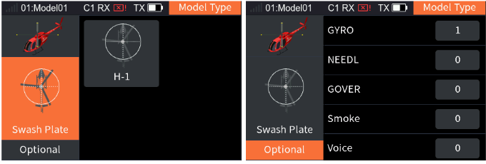
- Select [Model Type] > [Helicopter].
- Since the helicopter's Swash Plate only includes [H-1], you can directly select [Optional] and set the appropriate functionality according to the actual model by short pressing the scroll wheel to save the settings.
When the model type is a multicopter, there is no need to set up related model parameters and features.
The following are the steps for setting up the ship's functions:
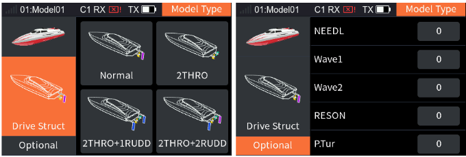
- Select [Model Type] > [Ship].
- Select [Drive Struct], set the drive structure according to the actual model and save the settings by short pressing the scroll wheel. Afterwards, it goes to the next setting automatically.
- Select [Optional], set the appropriate functionality according to the actual model by short pressing the scroll wheel to save the settings.
The following are the steps for setting up the car's functions; please refer to these steps for robot-related settings as well.
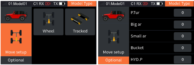
- Select [Model Type] > [Car].
- Select [Move setup], select the appropriate car type according to the actual model and short press the scroll wheel to save the settings.
- Select [Optional], set the appropriate functionality according to the actual model by short pressing the scroll wheel to save the settings.
6.2.4Model Copy
To copy the data of the selected model to another model. When a new model is to be set up, you can use this function to copy existing model data and then modify different parts without repeating the settings. It is very convenient.
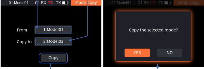
- Select [Mode Copy] to enter the function interface.
- Select the model to be copied to.
- Select [Copy]; the system displays a pop-up window, and choosing [Yes] means the copy is successful.
6.2.5Model Reset
Reset all model data for the current model. Note: Binding information will not be reset.
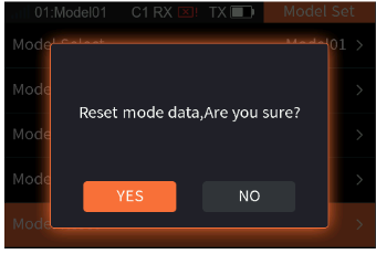
Setup: Select [Model Reset]; the system displays a pop-up window, and selecting [Yes] completes the reset.
6.3Reverse
To reverse the output direction of each channel.
This function can be used to correct the direction of the servo action which is opposite to the intended operation, due to different servo types or servo installation methods. Servo directions can be set for 16 channels.
- [NOR]: Indicates that the channel output is the default direction.
- [Reverse]: Indicates that the channel's direction has been reversed.
Notes:
- If a new model is connected, make sure the corresponding channel of the servo is correct.
- Move the controls related to the channels to make sure that the direction of each channel is correct.
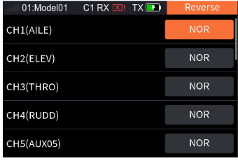
- Select [Reverse] to enter the function interface.
- Scroll the wheel to select the channel you want to set, and short press the scroll wheel to switch between [NOR] and [Reverse].
6.4Servo Rote (include Sub Trim)
Adjust the travel range of the servo output, which is used during the model debugging process. This function allows you to set the high and low endpoints for each channel, as well as the neutral position value.
This function can be used to solve the problem of angle difference between the servo and model structure when the servo is installed, or due to the structural inherent clearance of the servo. When you set the subtrim, toggle the trim to the neutral position first.
The Servo Rote adjustment range is 0%–150%, the default is 100%, the step is 1%. The Sub Trim adjustment range is −120%–120%, the default is 0%, the step is 1%.
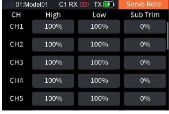
- Select [Servo Rote] to enter the function interface.
- Scroll the wheel to select the channel you wish to configure, and then choose the function item you want to set.
- Scroll the wheel to set the appropriate endpoints and neutral position value, then short press the scroll wheel to save the settings.
6.5Delay Set
This feature allows you to set the output speed of the channel. The easing time of start and centering can be set separately, that is, the easing time can be changed by different start and centering speeds.
You can use this function if you want to simulate the movement of a real aircraft or make up for the mechanical virtual position of the servo. After setting the easing time, all the volumes output from this channel execute the easing. The minimum delay is 0.0 s, and the maximum delay is 10.0 s. The adjustment step is 0.01 s.
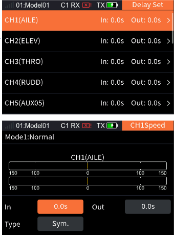
- Select [Delay Set] to enter the function interface.
- After scrolling the wheel to select the channel you want to set, enter the setup interface.
- Select the appropriate type as needed, then set In time and Out time; short press the scroll wheel to save the settings.
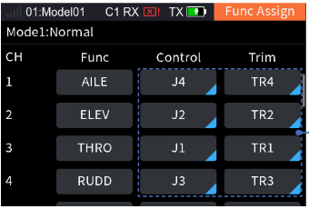
6.6Func Assign
Assign functions, controls and trim buttons to all channels. By default, the functions are assigned by model type after a new model is created. You can set the function here if you want to assign according to your habits.
6.6.1Assigning Function Items
To set the function controlled by each channel.
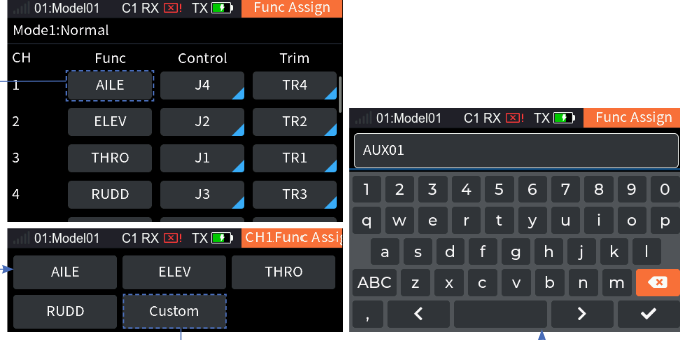
- Select the channel you want to set.
- Select the function item to enter the settings interface.
- Assign appropriate functions as needed. If you want to create an auxiliary channel for the control, select [Custom] to set an appropriate name, then select the check mark to return.
6.6.2Control Assign
To set specific controls corresponding to each channel. All controls except for the TR type and the shortcut buttons 1–6 can be assigned.
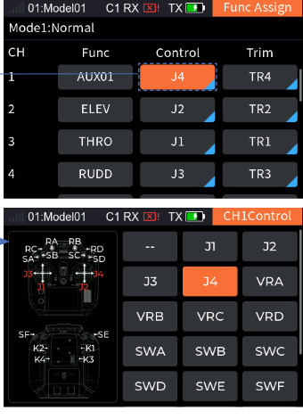
- Select the control item to enter the control settings interface.
- Scroll the wheel as needed to select the appropriate control or toggle the corresponding control, then short press the scroll wheel to confirm the setting.
- Short press the EXIT button to return.
You can set the related parameters after the control assignment is completed. The parameters are different for different controls.
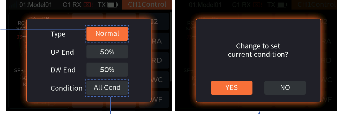
- For J1–J4 or VR controls, you can set [Type], [UP End], [DW End] and [Condition]. The adjustment range of the high end and low end is 20%–80%, the default is 50%, the step is 1%. You can set four types: [Normal], [Reverse], [UP End], [DW End]. [Normal] means that the corresponding control ratio changes from "−100% to 100%" when the control is moved from "down" to "up". It is conversely for Reverse: when the continuous control is moved from "down" to "up", the corresponding control ratio changes from "100% to −100%". For [DW End] and [UP End], the control ratio only switches between −100% and 100%. Selecting [UP End] means the control ratio is 100% in the high position and −100% in the low position. It is conversely for [DW End].
Take VRA as an example:
- After selecting [VRA], you will enter the parameter settings interface.
- Choose the appropriate type as needed.
- Set the appropriate high-end or low-end values as needed.
- Short press the scroll wheel to switch [All Cond] or [Current]; the system will display a pop-up window, and selecting [Yes] confirms the setting.
- Short press the EXIT button to return.
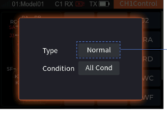
- For SW or K controls, you can set [Normal] and [Condition]. Function settings refer to the VRA function settings. You can set two types: [Normal] and [Reverse]. [Normal] means the control ratio is −100% when the control position is in the low position and 100% when the control position is in the high position (the neutral position control ratio in the three-level switch is 0%). [Reverse] is conversely: the control ratio of the control is 100% in the low position and −100% in the high position.
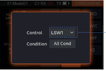
- For logic switches, you cannot set the parameters. When the control is ON, the control ratio is 100%; OFF means the control ratio is −100%. Function settings refer to the VRA function settings. You can set four controls: LSW1, LSW2, LSW3 and LSW4.
6.6.3Function Trim Assignment
To assign trim buttons corresponding to each channel.
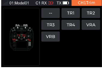
- Select [Trim] to enter the trim setting interface.
- Scroll the wheel as needed to select the appropriate control or toggle the corresponding control, then short press the scroll wheel to confirm the setting.
- Short press the EXIT button to return.
You can set the related parameters for the trim button after the trim assignment is completed. [Trim Mode], [Trim Rate] and [Condition] can be set.
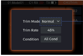
- Trim Mode: You can set four trim modes: [Normal], [Cen Max], [H-Max] and [L-Max]. [Normal] means normal trimming (linear) operation. [Cen Max] means the maximum trim adjustment in the neutral position, and no trim adjustment in the lowest and highest positions. [L-Max]: the adjustment amount is the greatest at the lowest position, and it decreases as it gets closer to the highest position, until it reaches 0 at the highest position. [H-Max]: the adjustment amount is the greatest at the highest position, and it decreases as it gets closer to the lowest position, until it reaches 0 at the lowest position.
- [Trim Rate]: The total travel range of the channel that can be controlled by the trim button. A negative value indicates the reverse. The adjustment range of the trim rate is −150%–150%, the default is 45%, the step is 1%.
Taking TR1 as an example, the parameter settings are as follows:
- Select [TR1] to enter the parameter setting interface.
- Select [Trim Mode], select the appropriate trim mode from the dropdown menu.
- Set the appropriate rate as needed.
- Short press the scroll wheel to switch [All Cond] or [Current]; the system displays a pop-up window, select [Yes] to confirm the setting.
- Short press the EXIT button to return.
6.7Trim
You can view the trim values of TR1 to TR4 and VRA to VRB in this preview interface. For TR1 to TR4, you can set the appropriate step value and the current condition/all conditions. For VRA to VRB, you can set the current condition/all conditions.
During use, a model's control surfaces may deflect in some situations, such as a centre-of-gravity shift or anti-torque force produced by aerodynamics. You can use this function to correct it during flight to keep a stable state. Please re-adjust the model in case the overall excessive offset of the model cannot be corrected by the trim function.
The adjustment range of the trim value is −100%–100%, the default step is 5%.
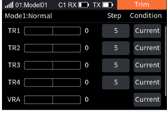
- Select [Trim] to enter the function setting interface.
- Scroll the wheel to select the corresponding trim control. If you select a TR control, you can adjust the step value as needed.
- Select [Condition], short press the scroll wheel to switch between [Current] and [All] mode.
- Adjust the trim value by operating the corresponding trim control.
6.8Timer
You can set up four types of timers: [Timer1], [Timer2], [Engine Timer] and [Model Timer]. They are generally used to calculate the total model running time, the time spent in specific competitions or the transmitter running time, etc.
6.8.1Timer1/2
[Timer1] and [Timer2] have the same function. Only one timer setting method is introduced below.
![Timer with Type Timer1, Mode Up, Alarm 0 M 0 s, Alarm Sound, Start Off, Stop Off, Reset Off, HomeDis 1; and the Home screen with the two timer areas [1] and [2]](/manuals/fs-st16/screens-timer.png)
- [Mode]: You can choose between [Up] and [Down]. [Up]: start timing from zero. [Down]: start timing down from the set time. After the down timer, continue timing as an up timer.
- [Alarm]: Set the timer alarm time. For the timer reminder, you can choose [Sound], [Sou+Vib] and [Vibration].
- [Start]: For starting the timer, corresponding controls can be assigned.
- [Stop]: For stopping the timer, corresponding controls can be assigned.
- [Reset]: Reset the timer value to its initial state; corresponding controls can be assigned.
- [Home Dis]: Set whether the timer is displayed in the timer area on the Home page; you can select [1], [2] and [None]. [1]: display in the first timer area on the Home page. [2]: display in the second timer area on the Home page. [None]: do not display in the timer area on the Home page.
Note: If multiple timers have the same [Home Dis] setting, the original settings will be overridden. For example, if you first set Timer1's [Home Dis] to [1], and then set Timer2's [Home Dis] to [1], the first area of the home page timer will display Timer2.
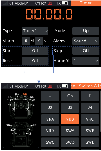
- Select [Timer] to enter the function setting interface.
- Select [Type] > [Timer1].
- Select [Mode], short press the scroll wheel to switch the timer mode.
- Select [Alarm], set the alarm time and the reminder.
- Select [Start], [Stop], and [Reset] respectively to enter the Switch Allocation interface. Scroll the wheel as needed to select the appropriate control or toggle the corresponding control, then short press the scroll wheel to confirm the setting.
- Set whether Timer1 is displayed in the timer area on the Home page and its display position.
Note: Please refer to 15. Switch Allocation for the switch setting.
6.8.2Engine Timer
Turn on the timer by setting the throttle trigger value and calculate the operating time of the throttle above the trigger value. The adjustment range of the trigger value is 0%–100%. The Engine Timer is off by default.
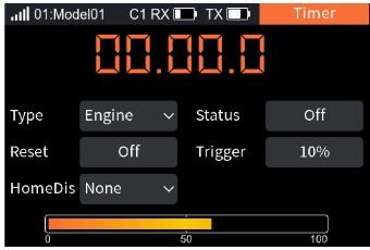
- Select [Type] > [Engine].
- Select [Status], short press the scroll wheel to switch [On] or [Off].
- Select [Reset] to enter the Switch Allocation interface. Scroll the wheel as needed to select the appropriate control or toggle the corresponding control, then short press the scroll wheel to confirm the setting.
- Set whether the Engine Timer is displayed in the timer area on the Home page and its display position.
- Set the trigger value as needed, short press the scroll wheel to save the settings.
Note: Please refer to 15. Switch Allocation for the switch setting.
6.8.3Model Timer
To calculate the total working time of the model. The Model Timer is off by default.
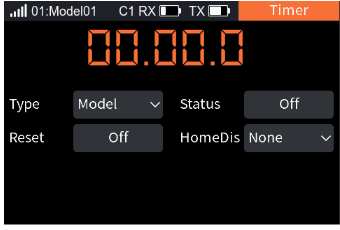
- Select [Type] > [Model].
- Select [Status], short press the scroll wheel to switch [On] or [Off].
- Select [Reset] to enter the Switch Allocation interface. Scroll the wheel as needed to select the appropriate control or toggle the corresponding control, then short press the scroll wheel to confirm the setting.
- Set whether the Model Timer is displayed in the timer area on the Home page and its display position.
Note: Please refer to 15. Switch Allocation for the switch setting.
6.9Trainer Mode
The FS-ST16 transmitter supports two function modes: Trainer and Student. The transmitter set to trainer mode receives the external signal to control the model, namely the trainer port has the ability to recognize external PPM signal input. The transmitter set to student mode only outputs the PPM signal. Two transmitters (one in trainer mode and the other in student mode) can be connected through the trainer cable.
Notes:
- When connecting two transmitters with a trainer cable, please make sure that the trainer cable is connected correctly.
- The transmitter's trainer port can adaptively recognize the input PPM signal. Most devices supporting PPM output can be used as the external input signal source of trainer mode. However, some devices may not support this function. The PPM output of the trainer port can be set to match external devices with special PPM signal recognition requirements.
When the trainer and student transmitters are properly connected, the relationship between the control switch states for the student and trainer and the actual control source is shown in the table below.
| Trainer control | Student control | Actual control |
|---|---|---|
| ON | ON | Trainer |
| ON | OFF | Trainer |
| OFF | ON | Student |
| OFF | OFF | Trainer |
6.9.1Trainer Mode
When the trainer mode is set to trainer, the transmitter only supports the functions of trainer mode. At this time, you can set the matched student mode transmitter through the trainer feature and controls to realize the application of the trainer transmitter function.
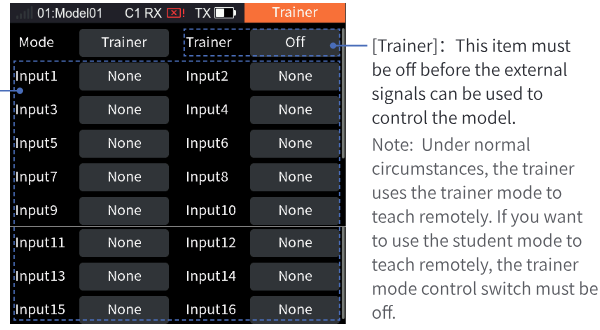
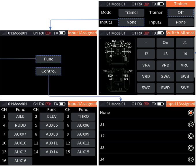
- Select [Trainer] to enter the function setting interface.
- Select [Mode] > [Trainer].
- Enter the Trainer Control switch allocation interface. Scroll the wheel as needed to select the appropriate control or toggle the corresponding control, then short press the scroll wheel to confirm the setting.
- Select [Input1–16] to enter the assigning interface as needed. Select [Func] to enter the setting interface, then select the appropriate function item. Select [Control] to enter the setting interface, then select the appropriate control.
- Short press the EXIT button to return.
Note: Please refer to 15. Switch Allocation for the switch setting.
6.9.2Student Mode
When the trainer mode is set to student, the transmitter supports only the functions of student mode. At this time, you can assign the control for the student control function and set the PPM signal parameters, such as signal polarity, channel number, period, and start identifier, to match the trainer mode transmitter and implement the trainer function application.
- [Student]: Performs the switching to indicate whether the student accepts control or not. Normally, this switch state is effective when the Trainer control of trainer mode is disabled.
- [Signal]: High level is valid by default (positive). Some devices may recognize low level as the valid signal. In that case, set the signal polarity to negative, that is, low level is valid.
- [Num. CH]: Set the number of channels in a PPM signal. By default, a PPM signal contains 8 channels; the number of channels can be set as needed, the setting range is 4–16.
- [Cycle]: Refers to the time of transmitting a PPM signal. The standard 8-channel PPM signal period is 20 ms. When fewer channels are used, a shorter period can be set to shorten the time required to send a signal and reduce latency. However, the setting of the period can only shorten the idle period, not the effective signal duration. Therefore, the setting of the period will not reduce the number of signal channels. When the number of channels increases and the effective signal sending time is greater than the period, the system will process the signal in minimum idle mode, and the interface setting value will not be changed accordingly.
- [Level]: The start mark time that identifies the PPM signal. The default value is 400 µs. Set the appropriate value as needed; the range is 100–700 µs.
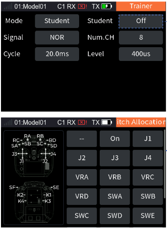
- Select [Trainer] to enter the function setting interface.
- Select [Mode] > [Student].
- Enter the Student Control switch allocation interface. Scroll the wheel as needed to select the appropriate control or toggle the corresponding control, then short press the scroll wheel to confirm the setting.
- Select [Signal], short press the scroll wheel to switch [NOR] or [REV].
- Select [Num. CH], scroll the wheel to set the number of channels and short press the scroll wheel to save the settings.
- Select [Cycle], scroll the wheel to set the period and short press the scroll wheel to save the settings.
- Select [Level], scroll the wheel to set the start identifier time and short press the scroll wheel to save the settings.
Note: Please refer to 15. Switch Allocation for the switch setting.
6.10Stick Mode
The system supports four stick modes. For aircraft models, CH1–4 are mapped by default to "ailerons, elevator, throttle, and rudder" respectively (J1, J2, J3, J4 represent CH3 throttle, CH2 elevator, CH4 rudder, CH1 ailerons). To accommodate different user preferences, the transmitter's stick presets support 4 different layout settings. You can choose between [Mode 1], [Mode 2], [Mode 3], or [Mode 4] to indicate the current selected mode (the system defaults to [Mode 2]). After selection, return and adjust the gimbal assembly according to the chosen mode and operational requirements. Please select the appropriate mode based on your actual needs and follow the steps below.
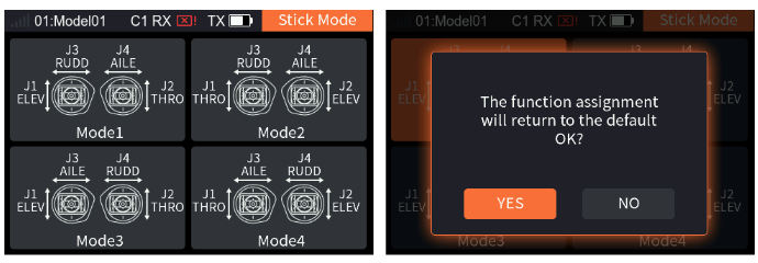
- Select [Stick Mode] to enter the function setting interface.
- Set the corresponding mode as needed; the system displays a pop-up window, selecting [Yes] means the setting is successful.
- Short press the EXIT button to return.
6.11SW Setting
This function is used to set up whether SWA, SWB, SWC, SWD, SWE and SWF are two-position or three-position switches. If these six switches need to be replaced, you can use this function to set the positions of the new switches.
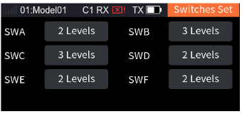
- Select [SW Setting] to enter the function setting interface.
- Select the switch you want to set, and then short press the scroll wheel to toggle between [2 Levels] and [3 Levels].
6.12Quick Set
To set the functions for shortcut buttons 1 to 6, so that pressing the corresponding button will quickly access that function. The serial numbers 1 to 6 represent shortcut buttons 1–6.
Note: Shortcut buttons 1 to 6 are only effective on the Home page.
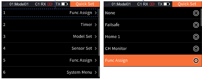
- Select [Quick Set] to enter the function setting interface.
- Select a number to enter the quick function setting interface, scroll the wheel to select the corresponding function item.
- Short press the EXIT button to return.
7Fixed-wing/Glider Exclusive Function Setting
This chapter introduces the function settings of fixed-wing/glider models mainly in the default condition. After you have set the related model parameters via [Basic Menu] > [Model Set], you can access the Model Menu to set the related functions of the model via [Main Menu] > [Model Menu].
Note: The function interface may differ based on different model configurations.
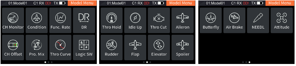
7.1CH Monitor
Please refer to 6.1 CH Monitor for this function.
7.2Condition
You can set different flight modes, with a maximum of 5 flight mode groups. A control can be set to quickly switch between different transmitter settings to ensure that the model's settings are adapted to the current flight conditions. Flight mode 1 is the default mode for the transmitter. Users can delete, create, or copy flight modes as needed, and except for the default mode, a control must be assigned to switch modes. You can also set the default flight mode by adjusting the priority order; when a mode is moved to the top of the interface, it becomes the default flight mode. The current flight mode can be determined through the flight mode icon in the system's top status bar and the interfaces related to flight mode settings.
Notes: Different parameters can be set for multiple functions of this transmitter by switching conditions, to perform control operations in different conditions according to different setting parameters. The details are as follows:
- For [Func Assign], different assignments of control and trim can be set for different conditions, or the same for all conditions.
- For [DR setup], the effective condition can be selected (multiple choices). The DR effectiveness of switching in different conditions may be different.
- Other items related to the condition can be set separately by switching conditions, and the channel operation is executed according to this condition. These setting items are contained in the following function interfaces: [Func. Rate], [CH Offset], [Pro. Mix], [Delay Set], [Thro Curve], [Aileron], [Flap], [NEEDL], [Air Brake], [Spoiler], [Elevator], [Rudder], [Butterfly], [V Tail], [Thro Mix], [Pitch Curve], [Hover Adj], [Gyroscope], [Governor].
7.2.1Rename
To rename the condition selected.
Setup: Select [Rename] to enter the editing interface, set the name as needed, then select the check mark to confirm the setting and return to the previous interface.
Note: It supports up to twelve characters.
7.2.2Set Switch
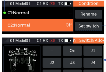
To set a control to switch among the conditions.
Setup: Select [Set switch] to enter the Switch Allocation interface, scroll the wheel as needed to select the appropriate control or toggle the corresponding control, then short press the scroll wheel to confirm the setting; short press the EXIT button to return.
7.2.3Creating A New Condition
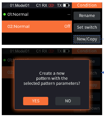
To create a new condition.
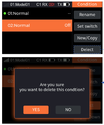
Setup: Select [New/Copy]; the system displays a pop-up window, select [Yes] to confirm the setting.
7.2.4Deleting A Condition
To delete a condition selected.
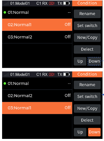
Setup: Select the condition you want to delete, then choose [Delete] to display a pop-up window. Selecting [Yes] will confirm the deletion.
Note: If there is only one condition, you cannot delete it; there is no Delete function item.
7.2.5Change Priority
Changes the order of the conditions so as to change the priority. The condition corresponding to serial number 5 has the highest priority, and number 4 is the next highest. The system works in this way according to this sequence.
Note: If there is only one condition, it is not possible to set a switch or priority. The default condition is number 1.
7.3Func. Rate
You can set servo volume change curves of all sticks, knobs, and switches assigned to the channel. You can switch to different conditions to set different curves respectively. The servo volume change curve for the conditions controlled by DR is set after enabling the DR. Those not supporting the assignment of the master control, such as Flap 2, cannot be set. The allocation of the same function of different channels from any setting entrance into the settings is the same.
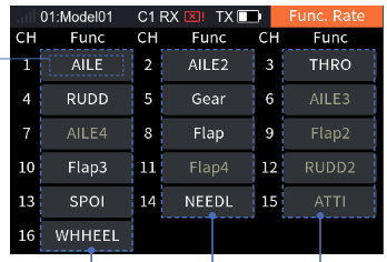
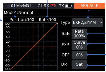
Note: When the curve type is set to [EXP2, Line], Rate A refers to the rate on the left side of the neutral, while Rate B refers to the rate on the right side of the neutral. Curve A is the curve on the left side of the neutral, and Curve B is the curve on the right side. Both sides A and B can be adjusted independently. When the curve type is set to [EXP2, SYMM] or [EXP1], the rate and curve items are not divided into A and B sides and are adjusted as a whole.
7.3.1Curve Type Setup
Set the curve type.
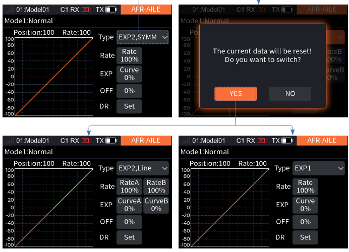
- Select the corresponding channel rate to enter the setting interface.
- Switch [Type] as needed; the system displays a pop-up window, and selecting [Yes] indicates that the switch has been successful.
7.3.2Setting Rate/EXP/Offset
Set the related Rate, EXP and Offset after a line type has been set. Take the Rate setting as an example.
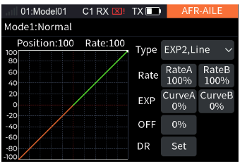
- Select [Type] > [EXP2, Line].
- Select [Rate A], scroll the wheel to adjust the percentage of Rate A, and then short press the scroll wheel to save the settings. For the setup steps of [Rate B], please refer to the above.
Note: For the setting of EXP and Offset, refer to the setting of Rate.
7.4DR
Set the function, switch and effective condition to enable the DR. The transmitter supports 10 groups of DR. When 2 or more sets of DR are set to the same function and both are turned on, the later one has higher priority.
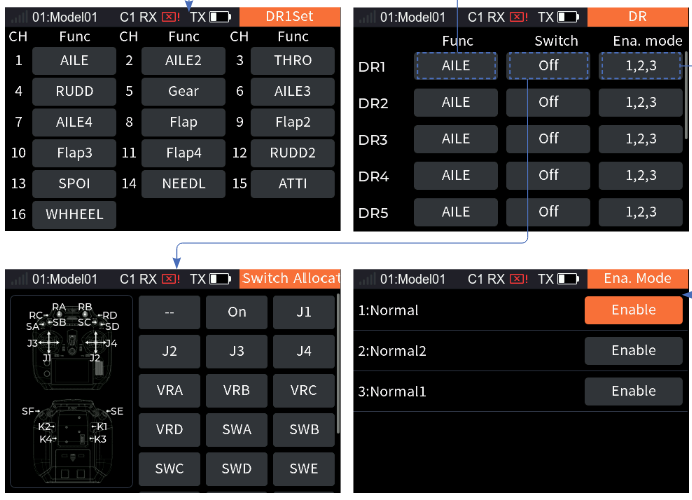
- Select [DR] to enter the function setting interface, then select DR1–10 as needed.
- Select [Func.] to enter the function assigning interface, then select the function item and short press the scroll wheel to save the settings.
- Select [Switch] to enter the Switch Allocation interface, scroll the wheel as needed to select the appropriate control or toggle the corresponding control, then short press the scroll wheel to confirm the setting.
- Select [Ena. mode] to enter the mode setting interface, enable or disable the corresponding mode as needed.
- Short press the EXIT button to return.
Note: Please refer to 15. Switch Allocation for the switch setting.
7.5CH Offset
This function allows you to adjust the offset value of each channel, and you can set different offset values in different conditions. The offset caused by the model can be corrected using this function. Too much offset will lead to a reduction of the control amount at one end of the channel. If the aircraft structure deviates greatly, please try to adjust the aircraft first.
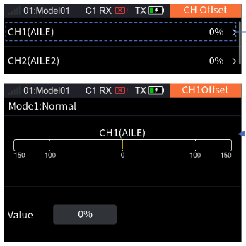
- Select a channel you want to adjust to enter.
- Select [Value], scroll the wheel to set the offset value and short press the scroll wheel to save the settings.
7.6Pro. Mix
A new special control combo can be created to correct the disadvantages of the model. You can select a stick/knob or a function as the Master. When selecting a function, you can set whether other mixes associated with the function affect the Slave of the same group and whether the trim affects the Slave. The function can be used to map the servo change of the Master to the Slave channel through a custom curve. You can set a switch to enable/disable the Mix, and set the delay to enable/disable the Mix function. Please note that if the master is set to ease by Set by function in the Servo speed function, the Slave will also follow the Master's easing.
It can be used for a variety of applications: link with other mixes, separate link settings for the master and slave with reversal of the connection direction; trim mode enabled or disabled; and curve mixing rate and mixing delay can be set separately for each group of Mix.
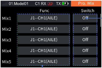
7.6.1Pro. Mix – Mixing Settings
Related settings for the Mix.
Master selection: Set the related settings of Master. Master can be set to a control or a function.
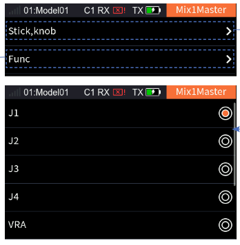
- Select the function box next to Master to enter.
- Select [Stick, knob] to enter if you want to set Master to a control. Select the desired control you want to set. Then short press the EXIT button to return to the previous interface. Select [Func] to enter if you want to set Master to a function. Select the desired function you want to set. Then short press the EXIT button to return to the previous interface.
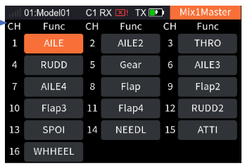
For Slave, you can only set it to a function; for the function setting of Slave, please refer to the descriptions of Master above.
Master Link/Slave Link: The link can be set for Master and Slave when Master is set to a specific function. The Link sets whether the master function will affect the slave function when it is affected by other mixes. Slave Link achieves the result of this group of mixers being used as a source of link for other mixes, which select this group's slave function as their master.
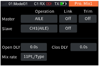
Setup: Select the function box below Master Link, short press the scroll wheel to switch [NOR], [Off] or [REV].
Note: NOR (normal) refers to a forward call, and REV (reverse) refers to a reverse call. When Master Link is set to Off, other function mixing volume will not affect Slave.
Take the link setting between Mix1 and Mix2 as an example:
| Mix 1 | Mix 2 | |
|---|---|---|
| Master | Func ELEV – Link Off | Func AILE – Link NOR or REV |
| Slave | Func AILE – Link NOR or REV | Func THRO – Link Off |
Note: When Master is set as a control, the Link and Trim functions are disabled, that is, the Link and Trim items will not appear.
Master Trim: Set the related trim settings of Master.
Setup: Select the function box below Master Trim, short press the scroll wheel to switch [Open] or [Off].
Note: When the trim is set to Open, Master trim changes will also affect Slave. When it is set to Off, Master trim changes will not affect Slave.
7.6.2Pro. Mix – Mixing Delay
Set the delay time for the current condition from triggering to taking effect for the Open delay or Close delay of the Mix. If the Mix delay needs to be set for other conditions, switch to other conditions prior to settings.
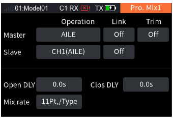
- Select [Open DLY] or [Clos DLY].
- Scroll the wheel to set the appropriate value and short press the scroll wheel to save the settings.
7.6.3Pro. Mix – Mixing Rate
Set the mix rate for the channel for the current condition.
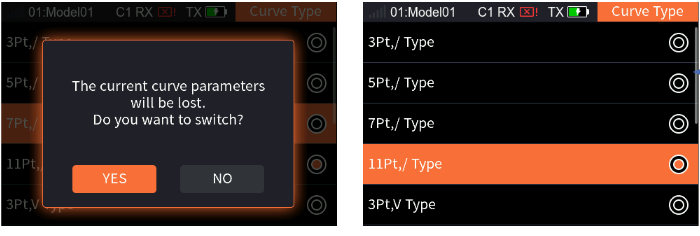
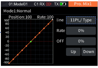
- Select [Line] to enter the interface if you want to change the line type and the number of dots.
- Select the appropriate curve type; the system displays a pop-up window, then select [Yes] to confirm the setting.
- Select [Up] or [Down] to select a dot as needed.
- Select [Rate] or [Point], set the appropriate percentage as needed and short press the scroll wheel to save the settings.
7.7Thro Curve
This function allows the throttle control lever to respond to engine speed changes more as expected to achieve the best results in the control of the engine. Different input and output rate factors (up to 11 points) are set through multi-point curves. The throttle curve will operate on the input values of all control levers assigned to the throttle function before the next step (Func. Rate). The multi-engine model throttle curve will operate for all throttle control levers. This setting is for the current condition. For the settings of other conditions, switch to other conditions first and then carry out the settings.
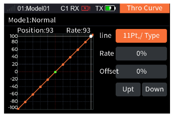
Please refer to 7.6.3 Pro. Mix – Mixing Rate for this function.
7.8Logic SW
A logic switch is a virtual switch consisting of 2 to 4 switches which activates or deactivates according to a mathematical relationship.
If there is any mathematical logic relationship between certain switch controls and the other two switch controls, this function can be used to express this logic and use it as a logic switch in control. The logic switch can be selected in any menu where switches can be assigned.
The system supports setting four groups of logic switches in total. There are three logic definitions between two switches: [AND], [OR], [XOR].
- [AND]: If switch1 and switch2 are active, the logic switch will be on. If either switch1 or switch2 is off, or both are off, the logic switch is off.
- [OR]: If either switch1 or switch2 is active, or both are on, the logic switch will be on. If both are off, the logic switch will be off.
- [XOR]: If either switch1 or switch2 is active, the logic switch will be on, but if switch1 and switch2 are both active or both off, the logic switch will be off.
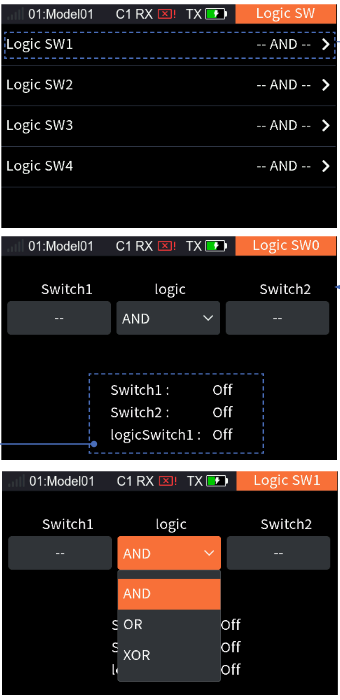
- Select a logic switch as desired and enter the setting interface.
- Select [Switch1] to enter the Switch Allocation interface, then select the appropriate switch and short press the EXIT button to return.
- Select [Switch2] to enter the Switch Allocation interface, then select the appropriate switch and short press the EXIT button to return.
- Select [Logic], select the logical operation from the dropdown box as needed (for the list, please refer to the table below).
- Toggle the switches to make sure everything is working as expected.
| Switch1 | Switch2 | AND | OR | XOR |
|---|---|---|---|---|
| Off | Off | Off | Off | Off |
| Off | On | Off | On | On |
| On | Off | Off | On | On |
| On | On | On | On | Off |
Notes:
- The setting of a logic switch makes sense only if it is composed of several other different switches.
- Please refer to 15. Switch Allocation for the switch setting.
7.9Thro Hold
Quickly locking the throttle channel output value at a preset value by one switch can assist in spin landing, or act as a throttle lock switch to lock the throttle position in a safe place during commissioning. This function is not valid when the Thro Cut switch is on. When the throttle hold is on, the mixes of the throttle from other functions are invalid. The throttle function is output after channel operations (Travel, Range, Normal and Reverse and channel delay) with the set hold value. The throttle function's mixes on other functions are also brought into operation using the value.
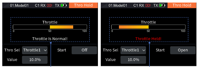
- Select the throttle as needed. The multi-engine model allows the separate setting of throttle hold functions for Throttle 1, Throttle 2, Throttle 3, and Throttle 4.
- Select [Value], scroll the wheel to set the throttle hold value and short press the scroll wheel to save the settings.
- Select [Start] to enter the Switch Allocation interface, then select the appropriate control and short press the scroll wheel to save the settings.
Note: Please refer to 15. Switch Allocation for the switch setting.
7.10Idle Up
This function can be used to set the throttle idle position, which can prevent the engine from shutting down when the throttle stick is in a lower position. The minimum throttle position is defined by setting the offset value. Once this function is activated, the minimum throttle setting (idle point) will be determined by the offset value shown as a percentage. For safety reasons, this function will work only when the throttle stick is below the lower position (−20%). The idle speed offset values of −100–0–100 correspond to a ratio factor of 80%–100–120%. The throttle control ratio will be multiplied with the ratio factor corresponding to the offset when the idle speed is enabled for the subsequent operation (throttle curve). When Thro Cut is enabled, the throttle hold and this function are not valid.
In multi-engine models, the idle switch is recognized only in the "throttle" control position (below −20%), and throttle, throttle 2, throttle 3 and throttle 4 will be calculated when the idle is enabled.
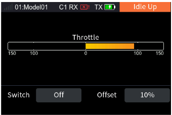
- Select [Switch] to enter the Switch Allocation interface, then select the corresponding control and short press the scroll wheel to save the settings.
- Select [Offset], scroll the wheel to set the appropriate offset value and short press the scroll wheel to save the settings. If the offset value is negative, it means the idle speed is rising. When the offset value is maximum, it indicates that the throttle stick is close to the minimum throttle.
Note: Please refer to 15. Switch Allocation for the switch setting.
7.11Thro Cut
This function is a special setting for oil-operated engines. The Cut switch, Cut position and Cut Threshold can be set. When the throttle control stick is within the Thro Cut threshold, toggle the Thro Cut switch to turn off the engine. The output value of the throttle function when Thro Cut is in effect is the Thro Cut position value. It will be limited by the channel reverse function and the channel range function, and all other volumes operated to the channel corresponding to this throttle are invalid. However, the other functions of throttle mixing still work.
Multi-engine models can set Thro Cut separately for throttle, throttle 2, throttle 3 and throttle 4.
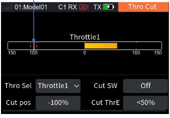
- Select the throttle as needed.
- Select [Cut SW] to enter the Switch Allocation interface, then select the appropriate switch and short press the EXIT button to return.
- Select [Cut pos], scroll the wheel to set the appropriate cut position and short press the scroll wheel to save the settings.
- Select [Cut ThrE], scroll the wheel to set the appropriate cut threshold and short press the scroll wheel to save the settings.
- Toggle the switch to confirm whether it works properly.
Note: Please refer to 15. Switch Allocation for the switch setting.
7.12Aileron
This section introduces the settings of the aileron and its mix functions.
The parameter settings of this function are for the current condition. To set in another condition, you need to switch the condition first.
Note: Due to the different model structures (for example, different numbers of ailerons and flaps), the corresponding function interface may be different. Usually, up to four ailerons are described as an example.
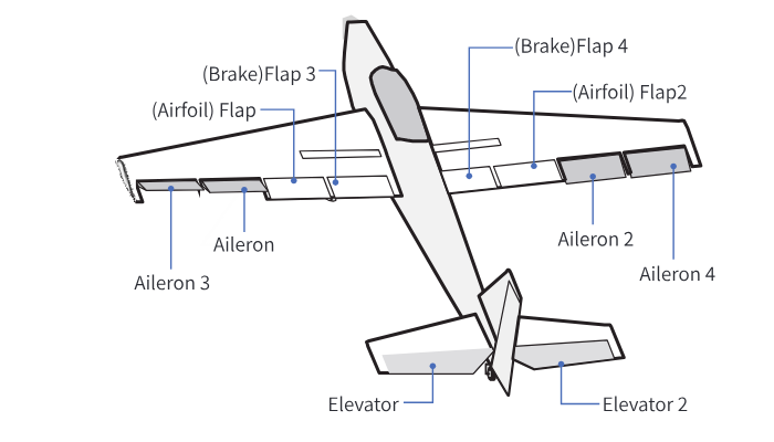
7.12.1Aileron Differential
The left and right ailerons of the aircraft or glider can be adjusted independently. The differential aileron adjustment can be achieved by setting different high and low rate values for each aileron.
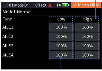
Take the setting of Low as an example: select [Low], set the corresponding rate items for the low end as needed, short press the scroll wheel to save the settings. For the setting of High, please refer to the above steps.
7.12.2Aileron Elevator
Sets the elevator with the aileron function to improve the model's roll performance. Only aircraft with two-elevator tails support this function. You can set the high and low rate values of the two elevators to move with the aileron function.
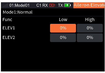
Take the setting of Low as an example: select [Low], set the corresponding rate items for the low end as needed, short press the scroll wheel to save the settings. For the setting of High, please refer to the above steps.
7.12.3Aileron Camber Flap
This mix function is used to set the linkage between the camber flap and the aileron so that the flap can work together with the aileron, thus improving the maneuvering characteristics around the longitudinal axis.
Note: This function is available for models with one flap or more.
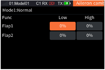
Take the setting of Low as an example: select [Low], set the corresponding rate items for the low end as needed, short press the scroll wheel to save the settings. For the setting of High, please refer to the above steps.
7.12.4Aileron Brake Flap
This mix function is used to set the linkage between the brake flap and the aileron so that the flap can work together with the aileron, thus improving the maneuvering characteristics around the longitudinal axis.
Note: This function is only available with 4 flaps.
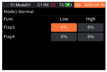
Take the setting of Low as an example: select [Low], set the corresponding rate items for the low end as needed, short press the scroll wheel to save the settings. For the setting of High, please refer to the above steps.
7.12.5Aileron To Elevator
Usually more lift is needed on ailerons when turning/rolling. This function allows you to set the compensation rate of the elevator during aileron movement, so that the elevator will be subject to a compensatory trim according to the set rate during aileron movement, thus preventing the nose-down of the aircraft.
Note: If the model structure is a tailless (flying wing) aircraft, the aileron can be used as an elevator. This setting will affect all elevator surfaces, and even the aileron surfaces in the case of a tailless aircraft.
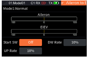
Take the setting of DW Rate as an example:
- Select [DW Rate], set the corresponding rate items for the low end as needed, short press the scroll wheel to save the settings.
- Select [Start SW] to enter the Switch Allocation interface, then select the appropriate switch and short press the EXIT button to return.
Note: Please refer to 15. Switch Allocation for the switch setting.
For the setting of UP Rate, please refer to the above steps.
7.12.6Aileron To Rudder
This mix function is used to set the linkage between the rudder servo and the aileron. This function can be set to achieve more coordinated and flexible steering and roll through the compensatory trim of the steering servo during the aileron movement.
Note: When there are two rudders, rudder 1 and 2 will both be affected.
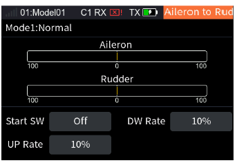
Take the setting of DW Rate as an example:
- Select [DW Rate], set the corresponding rate items for the low end as needed, short press the scroll wheel to save the settings.
- Select [Start SW] to enter the Switch Allocation interface, then select the appropriate switch and short press the EXIT button to return.
Note: Please refer to 15. Switch Allocation for the switch setting.
For the setting of UP Rate, please refer to the above steps.
7.13Rudder
This section introduces the settings of the rudder and its mix functions.
The parameter settings of this function are for the current condition. To set in another condition, you need to switch the condition first.
Note: Due to the different model structures (for example, different numbers of ailerons and flaps), the corresponding function menu may be different.
7.13.1Rudder LINK
This function is applicable to models with winglets, and is used to adjust the winglet rudder angle. The winglets are used to solve the wingtip vortex problem, thus reducing the induced drag and improving efficiency. The winglets are usually symmetrically erected vertically at both wingtips or extended outward at a certain angle.
Winglets increase the effective aspect ratio without significantly increasing the wing load and weight. Although the induced drag can be effectively reduced by extending the wing, this will also increase the parasitic drag and wing load strength at the same time, resulting in an insignificant gain. The winglets can effectively increase the aspect ratio without increasing the wingspan.
Note: This function is available for models with tailless-2RUD.
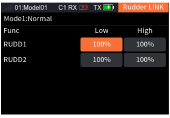
Take the setting of Low as an example: select [Low], set the corresponding rate items for the low end as needed, short press the scroll wheel to save the settings. For the setting of High, please refer to the above steps.
7.13.2Rudder To Aileron
This mix function is used to set the linkage between the rudder and the aileron. It is used to adjust the rate at which all control surfaces affecting the airfoil change according to the airfoil. You can adjust with the two sides (Up/Down), and meanwhile you can correct the effect of these control surfaces on the direction of flight.
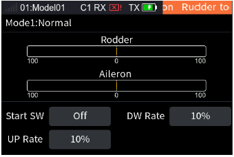
Take the setting of DW Rate as an example:
- Select [DW Rate], set the corresponding rate items for the low end as needed, short press the scroll wheel to save the settings.
- Select [Start SW] to enter the Switch Allocation interface, then select the appropriate switch and short press the EXIT button to return.
Note: Please refer to 15. Switch Allocation for the switch setting.
For the setting of UP Rate, please refer to the above steps.
7.13.3Rudder To Elevator
This mix function is used to set the linkage between the rudder and the elevator. This function is used when it is necessary to realize the linkage between the elevator and rudder, to correct the offset in the pitching direction when the aerobatic model aircraft is turning and flying laterally. For tailless aircraft, aileron 2 is used to replace the elevator to achieve the elevation function.
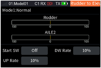
Take the setting of DW Rate as an example:
- Select [DW Rate], set the corresponding rate items for the low end as needed, short press the scroll wheel to save the settings.
- Select [Start SW] to enter the Switch Allocation interface, then select the appropriate switch and short press the EXIT button to return.
Note: Please refer to 15. Switch Allocation for the switch setting.
For the setting of UP Rate, please refer to the above steps.
7.14Flap
This section introduces the settings of the flap and its mix functions.
The parameter settings of this function are for the current condition. To set in another condition, you need to switch the condition first.
Note: Due to the different model structures (for example, different numbers of ailerons and flaps), the corresponding function interface may be different. Usually, up to four ailerons are described as an example.
7.14.1Flap Setting
This function is used to set the high and low end rates and offset of the flaps separately; that is, for a model with multiple flaps, the upward and downward travel and neutral point position of each flap can be adjusted independently.
Note: The number of flap function items in the interface is related to the Wing set in Models.
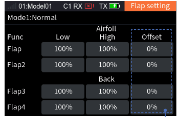
Take the setting of Low as an example: select [Low], set the corresponding rate items for the low end as needed, short press the scroll wheel to save the settings. For the setting of High, please refer to the above steps.
7.14.2Brake To Airfoil
This mix function is used to set the high to low rate of the brake flaps to the airfoil flaps. It is used to adjust the up/down movement travel range of multiple flaps independently.
Note: This function is only available with 4 flaps.
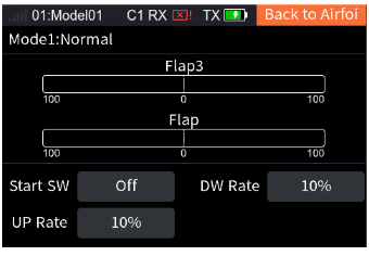
Take the setting of DW Rate as an example:
- Select [DW Rate], set the corresponding rate items for the low end as needed, short press the scroll wheel to save the settings.
- Select [Start SW] to enter the Switch Allocation interface, then select the appropriate switch and short press the EXIT button to return.
Note: Please refer to 15. Switch Allocation for the switch setting.
For the setting of UP Rate, please refer to the above steps.
7.14.3Airfoil To Elevator
This mix function is used to set the linkage between the airfoil flap and the elevator. You can set a compensatory trim for the elevator to prevent the aircraft from diving when the airfoil flap is operated to slow down.
For models with normal tail / V tail / Ailvator (double elevator) tails, the function item is only Elevator/Elevator 2. For those having ailerons but without tail (there is no elevator function item; the number of aileron function items is subject to the actual number of ailerons), set the aileron as the elevator, so as to use the Airfoil to Elevator function.
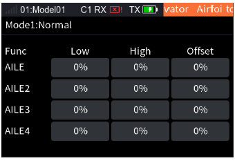
Take the setting of Low as an example: select [Low], set the corresponding rate items for the low end as needed, short press the scroll wheel to save the settings. For the setting of High, please refer to the above steps.
7.14.4Brake Flap To Elevator
This mix function is used to set the linkage between the brake flap and the elevator. You can set a compensatory trim for the elevator to prevent the aircraft from diving when the brake flap is operated to slow down.
Note: This function is only available with 4 flaps.
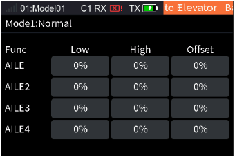
Take the setting of Low as an example: select [Low], set the corresponding rate items for the low end as needed, short press the scroll wheel to save the settings. For the setting of High, please refer to the above steps.
7.15Elevator
This section introduces the settings of the elevator and its mix functions.
The parameter settings of this function are for the current condition. To set in another condition, you need to switch the condition first.
Notes:
- Due to the different model structures (for example, different numbers of ailerons and flaps), the corresponding function menu may be different.
- The aileron movement mode is not restricted in the mixing linkage of the elevator and aileron.
7.15.1Elevator Linkage
This mix function is used to adjust the rise and fall rates of the left and right elevators separately.
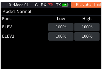
Take the setting of Low as an example: select [Low], set the corresponding rate items for the low end as needed, short press the scroll wheel to save the settings. For the setting of High, please refer to the above steps.
7.15.2Elevator Aileron
This mix function is used to set the linkage between the elevator and aileron. For models with an elevator, the elevator can link the aileron to move in the same direction to increase the lift. For models without tail, the aileron 2 master control can be used to link the aileron to move in the same direction to achieve the rise and fall function.
Note: This function item is not available for single-aileron models. For multi-aileron models, the number of aileron function items depends on the actual number of ailerons.
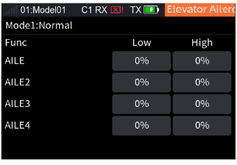
Take the setting of Low as an example: select [Low], set the corresponding rate items for the low end as needed, short press the scroll wheel to save the settings. For the setting of High, please refer to the above steps.
7.15.3Elevator To Airfoil
This mix function is used to set the linkage between the elevator and the airfoil flap. When this function is enabled, the elevator/aileron 2 master control of the model will affect the airfoil flap proportionally, thus increasing the lift of the model.
Note: For tail-less aircraft, aileron 2 is used instead of the elevator.
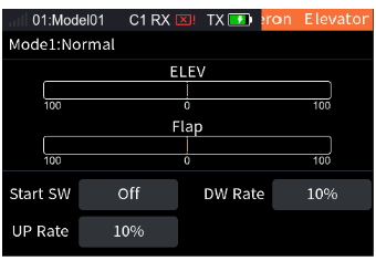
Take the setting of DW Rate as an example:
- Select [DW Rate], set the corresponding rate items for the low end as needed, short press the scroll wheel to save the settings.
- Select [Start SW] to enter the Switch Allocation interface, then select the appropriate switch and short press the EXIT button to return.
Note: Please refer to 15. Switch Allocation for the switch setting.
For the setting of UP Rate, please refer to the above steps.
7.15.4Elevator To Brake
This mix function is used to set the linkage between the elevator and the brake flap. When this function is enabled, the elevator/aileron 2 master control of the aircraft affects the brake flaps at the set rate, thus increasing the lift of the aircraft.
Note: This function is only available for models with 4 flaps. For tail-less aircraft, aileron 2 is used instead of the elevator.
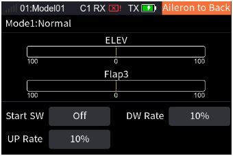
Take the setting of DW Rate as an example:
- Select [DW Rate], set the corresponding rate items for the low end as needed, short press the scroll wheel to save the settings.
- Select [Start SW] to enter the Switch Allocation interface, then select the appropriate switch and short press the EXIT button to return.
Note: Please refer to 15. Switch Allocation for the switch setting.
For the setting of UP Rate, please refer to the above steps.
7.16Spoiler
The spoiler, also called deceleration flap, can achieve fast braking by increasing the aircraft's pressure on the ground when the aircraft is descending. Meanwhile, the use of the spoiler in flight can also achieve the effect of aircraft deceleration. This function can be used to set the upward and downward movements of each spoiler and the linkage between spoiler and elevator. If the spoiler is used during deceleration, the aircraft will tend to dive. If the elevator linkage is set, the flight attitude can be controlled through the compensatory trim of the elevator.
The parameter settings of this function are for the current condition. To set in another condition, you need to switch the condition first.
Notes:
- Due to the different model structures (for example, different numbers of ailerons), the corresponding function menu may be different. Usually, up to four ailerons are described as an example.
- If it is a flying wing type aircraft, the elevator setting item is aileron; or, use the flap function to add setting interfaces for the aircraft.
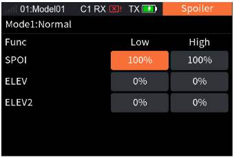
Take the setting of Low as an example: select [Low], set the corresponding rate items for the low end as needed, short press the scroll wheel to save the settings. For the setting of High, please refer to the above steps.
7.17Butterfly
This function realizes deceleration by adjusting the rates of ailerons, flaps, spoilers and elevator, i.e., ailerons are raised and flaps are lowered at the same time. This function is very effective when the model is landing, i.e., reducing the speed of the model; more stall margin is provided at the wingtip, thus less risk of wingtip stall. And more lift is generated at the root of the wing, allowing a lower gliding speed.
The parameter settings of this function are for the current condition. To set in another condition, you need to switch the condition first.
Note: This function is available for multi-flap airplanes.
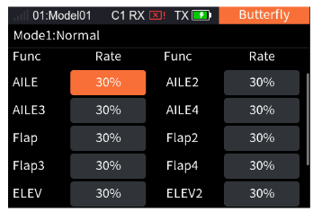
- Set the corresponding rate items as needed, short press the scroll wheel to save the settings.
- Select [Control] to enter the Switch Allocation interface, then select the appropriate switch and short press the EXIT button to return.
Note: Please refer to 15. Switch Allocation for the switch setting.
For the setting of the other functions, please refer to the above steps.
7.18Air Brake
When the model is ready to descend or land, the air brake function can be used to help decelerate. This function is achieved by setting the offset values of ailerons, spoilers and elevators.
The offset values of ailerons, flaps, spoilers and elevators can be set in two sets. Enable/disable the air brake and switch between different offsets by assigning controls.
The parameter settings of this function are for the current condition. To set in another condition, you need to switch the condition first.
Notes:
- Due to the different model structures (for example, different numbers of ailerons), the corresponding function menu may be different. Usually, up to four ailerons are described as an example.
- Two brake rates can be realized by setting a three-position switch with two positions corresponding to offset 1 / offset 2 respectively.
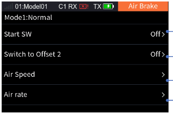
7.18.1Air Speed
Sets the parameters related to the brake speed function. You can set the time to complete the action when the brake is enabled and disabled. The longer the time, the slower the speed.
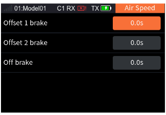
Take the setting of Offset 1 brake as an example: select [Offset 1 brake], set the appropriate time as needed and then short press the scroll wheel to save the settings. For the setting of Offset 2 and Off brake, please refer to the above steps.
7.18.2Air Rate
Sets the offsets of AILE, Flap, Spoiler and Elevator for the current condition. To set in another condition, you need to switch the condition first.
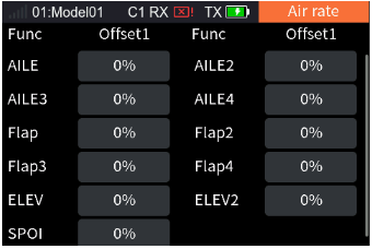
Take the setting of Offset 1 brake of AILE as an example: select the appropriate rate item as needed and then short press the scroll wheel to save the settings. For the setting of the other functions, please refer to the above steps.
7.19V Tail
This function is used to adjust the rate of the V-shaped tail's 2 tail fins in steering and pitching. The V-shaped tail aircraft performs the rudder and elevator movements via 2 servos. In this system, one of the tail surfaces implements the rudder function and the other performs the elevator function, corresponding to two channels respectively. When the rudder function is implemented, the two control surfaces move in opposite directions. When the elevator function is implemented, the two control surfaces move in the same direction. This interface allows you to set the elevator rate and rudder rate, i.e., the rate of the elevator is for realizing the elevator function and the rate of the rudder is for realizing the rudder function.
The parameter settings of this function are for the current condition. To set in another condition, you need to switch the condition first.
Note: This function is available for models with V Tail.
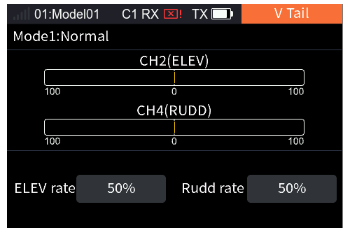
- Select [ELEV rate], then set an appropriate value as needed and short press the scroll wheel to save the settings.
- Select [Rudd rate], then set an appropriate value as needed and short press the scroll wheel to save the settings.
7.20NEEDL
The throttle needle function is set for models with a throttle needle. This function is used to set the output rate of the throttle needle master control with a multi-point curve.
For example, if you need to link a throttle to a needle, you can assign the throttle needle to be controlled by the throttle stick, and realize the control of the needle by the throttle stick by setting the curve.
The setting steps of the throttle needle are similar to those of the throttle curve. Refer to the related settings of 7.7 Thro Curve.
Note: To access this feature, you need to go to [Basic Menu] > [Model Set] > [Model Type] > [Optional], and select [NEEDL].
7.21Attitude
This function allows setting up to 9 output values for channels assigned with attitude functions. The output value of the channel can be switched via the set combo switch.
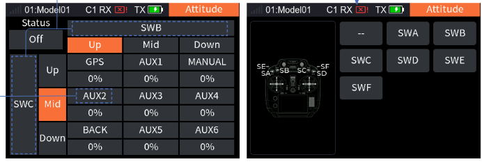
- Select [Attitude] to enter the setting interface.
- Select the function box with "--" to enter the switch assignment interface. Select a switch you want to set or toggle the corresponding control, then short press the scroll wheel to confirm the setting, then short press the EXIT button to return to the previous interface. After these two switches are assigned, the function and its output value are controlled by the combo switch.
- Select [Status] > [On] to enable the function.
- Scroll the wheel to select the function item that needs to be renamed. The system will display a rename interface; you can set the appropriate name and then select the check mark to return to the previous interface.
- If you need to change the rate value, scroll the wheel to select the rate item you want to change and set the appropriate value. After the settings are completed, short press the EXIT button to return.
Notes:
- The rate value indicates the output in percentage of a channel.
- Only toggle switches can be assigned.
- This function is not available for glider models.
8Helicopter Exclusive Function Setting
This chapter introduces the function settings of Helicopter models mainly in the default condition. After you have set the related model parameters via [Basic Menu] > [Model Set], you can access the Model Menu to set the related functions of the model via [Main Menu] > [Model Menu].
Note: The function interface may differ based on different model configurations.
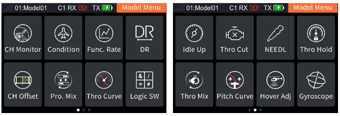
8.1CH Monitor
Please refer to 7.1 CH Monitor for this function.
8.2Condition
Please refer to 7.2 Condition for this function.
8.3Func. Rate
Please refer to 7.3 Func. Rate for this function.
8.4DR
Please refer to 7.4 DR for this function.
8.5CH Offset
Please refer to 7.5 CH Offset for this function.
8.6Pro. Mix
Please refer to 7.6 Pro. Mix for this function.
8.7Thro Curve
Please refer to 7.7 Thro Curve for this function.
8.8Logic SW
Please refer to 7.8 Logic SW for this function.
8.9Idle Up
Please refer to 7.10 Idle Up for this function.
8.10Thro Cut
Please refer to 7.11 Thro Cut for this function.
8.11NEEDL
Please refer to 7.20 NEEDL for this function.
8.12Thro Hold
Please refer to 7.9 Thro Hold for this function.
8.13Thro Mix
In the current condition, set the helicopter's ailerons, elevator and rudder to the throttle's mix rate. It is used to coordinate the flight movements of the helicopter in all directions (forward, backward, left and right) to compensate for the effect of swashplate manipulation on the engine when operating ailerons, elevator and rudder.
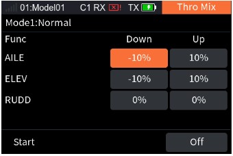
- Set the rate item as needed, short press the scroll wheel to save the settings.
- Select [Start] to enter the Switch Allocation interface, then select the appropriate switch and short press the EXIT button to return.
Note: Please refer to 15. Switch Allocation for the switch setting.
8.14Pitch Curve
In the current condition, adjust the motion curve of the helicopter's pitch to match the throttle output to achieve the best flight status. To set in another condition, you need to switch the condition first. Different output rates can be obtained through multi-point linear settings (up to 11 points).
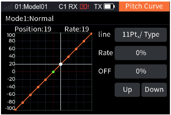
Please refer to 7.6.3 Pro. Mix – Mixing Rate for this function.
8.15Hover Adj
In the current condition, to allow the helicopter to hover easily, adjust the rates of Throttle and Pitch. To set in another condition, you need to switch the condition first.
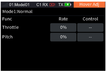
- Set the Throttle or Pitch rate item as needed, short press the scroll wheel to save the settings.
- Select the Throttle control to enter the Switch Allocation interface, then select the appropriate knob and short press the EXIT button to return.
- Select the Pitch control to enter the Switch Allocation interface, then select the appropriate knob and short press the EXIT button to return.
Note: For the control of the function, you can only set a knob.
8.16Gyroscope
Set the output value of the gyroscope channel.
The system is preset with two gyroscope modes (you can set the number of gyroscopes via [Basic Menu] > [Model Set] > [Model Type] > [Optional]). You can adjust the gyroscope channel output sensitivity.
The parameter settings of this function are for the current condition. To set in another condition, you need to switch the condition first.
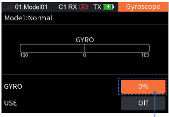
- Select the gyroscope you want to set, and set an appropriate sensitivity value as needed.
- Select [USE], short press the scroll wheel to switch [Off] or [On].
- Short press the EXIT button to return.
8.17Governor
Set the output value of the Governor channel to adjust the RPM of the helicopter rotor to make the helicopter fly more stably. The parameter settings of this function are for the current condition. To set in another condition, you need to switch the condition first.
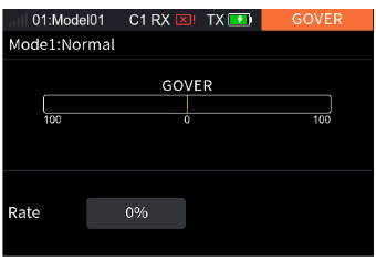
- Select [Rate], set the rotor speed value as needed.
- Short press the EXIT button to return.
9Multicopter Exclusive Function Setting
This chapter introduces the function settings of Multicopter models mainly in the default condition. After you have set the related model parameters via [Basic Menu] > [Model Set], you can access the Model Menu to set the related functions of the model via [Main Menu] > [Model Menu].
9.1CH Monitor
Please refer to 7.1 CH Monitor for this function.
9.2Condition
Please refer to 7.2 Condition for this function.
9.3Func. Rate
Please refer to 7.3 Func. Rate for this function.
9.4DR
Please refer to 7.4 DR for this function.
9.5CH Offset
Please refer to 7.5 CH Offset for this function.
9.6Pro. Mix
Please refer to 7.6 Pro. Mix for this function.
9.7Thro Curve
Please refer to 7.7 Thro Curve for this function.
9.8Logic SW
Please refer to 7.8 Logic SW for this function.
9.9Attitude
Please refer to 7.21 Attitude for this function.
9.10Thro Hold
Please refer to 7.9 Thro Hold for this function.
10Car Exclusive Function Setting
This chapter introduces the function settings of Car models mainly in the default condition. After you have set the related model parameters via [Basic Menu] > [Model Set], you can access the Model Menu to set the related functions of the model via [Main Menu] > [Model Menu].
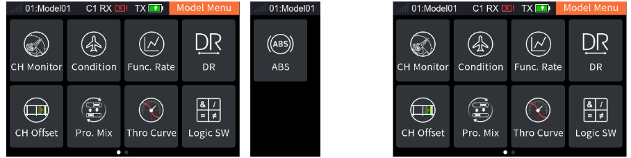
10.1CH Monitor
Please refer to 7.1 CH Monitor for this function.
10.2Condition
Please refer to 7.2 Condition for this function.
10.3Func. Rate
Please refer to 7.3 Func. Rate for this function.
10.4DR
Please refer to 7.4 DR for this function.
10.5CH Offset
Please refer to 7.5 CH Offset for this function.
10.6Pro. Mix
Please refer to 7.6 Pro. Mix for this function.
10.7Thro Curve
Please refer to 7.7 Thro Curve for this function.
10.8Logic SW
Please refer to 7.8 Logic SW for this function.
10.9ABS
This function can be used to set pulse braking, namely the brakes are released periodically when braking is triggered, to prevent skidding, drifting or under-turning due to locked wheels.
Note: This function is available for the Humvees model.
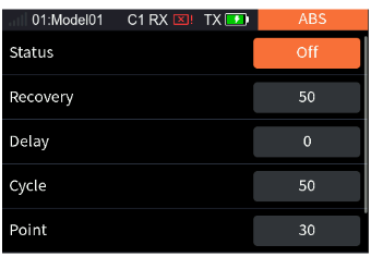
- [Status]: To activate or deactivate the ABS feature, short press the scroll wheel to switch between [On] and [Off].
- [Recovery]: To set the reduction of braking pressure at each pulse between 0% and 100%. The default value is 50%. When the value is set to 60%, the system will reduce the braking pressure by 60% from each pulse in real-time when braking is triggered.
- [Delay]: To set the time from triggering the pulse brake to the actual pulse brake between 0% and 100%. The default value is 0%. The higher the value, the slower the pulse brake function will take effect. When the value is set to 0%, there is no delay, i.e. the pulse brake function takes effect immediately when the brake is triggered. When the value is set to 100%, the delay is 2 s.
- [Cycle]: It is used to set the interval between pulses. The setting range is 20% to 100%. The default value is 50%. The larger the value, the longer the interval time between pulses. The value 100% indicates the interval is 0.5 s.
- [Point]: It is used to set the start position of the pulse brake function. The setting range is 20% to 100%. The default value is 30%. The higher the value, the closer the stick position that triggers the pulse brake function is to the full brake position. 0%–100% is the entire travel movement amount of the throttle control.
- [Duty]: To set the braking–release cycle length in pulse braking between −4 and +4. Default: 0. When the value is changed, the peak and trough lengths of the brake pulse's square wave change accordingly. You can adjust the ratio between braking and release. The rate is 1:1 when the cycle length is set to "0". The rate is 1:2 when the cycle length is set to "1". And the rate is 2:1 when the cycle length is set to "−1".
Taking the [Recovery] setting as an example: select [Recovery], set the appropriate value as needed, and short press the scroll wheel to save the settings. For the setting of the other functions, please refer to the above steps.
10.10Track Mix
When this function is enabled, the control corresponding to the left track can control the changes of the left and right tracks at the same rate to move forward and backward, and the control corresponding to the right track can control the changes of the left and right tracks at the reverse rate to turn left and right. The forward, backward, left and right rates can be set in the function menu.
Note: This function is available for the track model.
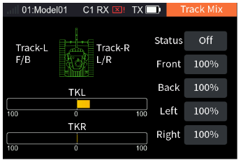
- Select [Status], short press the scroll wheel to switch [On] or [Off].
- Adjust the percentage values for forward, backward, left turn, and right turn as needed, then briefly press the scroll wheel to save the settings.
11Ship Exclusive Function Setting
This chapter introduces the function settings of Ship models mainly in the default condition. After you have set the related model parameters via [Basic Menu] > [Model Set], you can access the Model Menu to set the related functions of the model via [Main Menu] > [Model Menu].
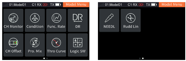
11.1CH Monitor
Please refer to 7.1 CH Monitor for this function.
11.2Condition
Please refer to 7.2 Condition for this function.
11.3Func. Rate
Please refer to 7.3 Func. Rate for this function.
11.4DR
Please refer to 7.4 DR for this function.
11.5CH Offset
Please refer to 7.5 CH Offset for this function.
11.6Pro. Mix
Please refer to 7.6 Pro. Mix for this function.
11.7Thro Curve
Please refer to 7.7 Thro Curve for this function.
11.8Logic SW
Please refer to 7.8 Logic SW for this function.
11.9Double Engine Mix
This function is enabled when the ship model has dual engines without rudders. The dual engine mix controls the forward/backward and left/right movement of the ship.
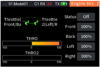
- Select [Status], short press the scroll wheel to switch [On] or [Off].
- Adjust the percentage values for forward, backward, left turn, and right turn as needed, then briefly press the scroll wheel to save the settings.
11.10Rudd Linkage
This function is enabled when the ship model has dual engines with two rudders to realize the rudder linkage output. The parameter settings of this function are for the current condition. To set in another condition, you need to switch the condition first.
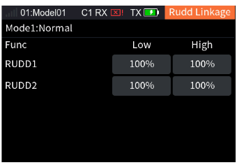
- Select the corresponding rate item.
- Set the high and low rate as needed, and then short press the scroll wheel to save the settings.
11.11NEEDL
Please refer to 7.20 NEEDL for this function.
12Robot Exclusive Function Setting
This chapter introduces the function settings of Robot models mainly in the default condition. After you have set the related model parameters via [Basic Menu] > [Model Set], you can access the Model Menu to set the related functions of the model via [Main Menu] > [Model Menu].
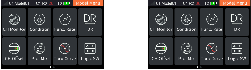
12.1CH Monitor
Please refer to 7.1 CH Monitor for this function.
12.2Condition
Please refer to 7.2 Condition for this function.
12.3Func. Rate
Please refer to 7.3 Func. Rate for this function.
12.4DR
Please refer to 7.4 DR for this function.
12.5CH Offset
Please refer to 7.5 CH Offset for this function.
12.6Pro. Mix
Please refer to 7.6 Pro. Mix for this function.
12.7Thro Curve
Please refer to 7.7 Thro Curve for this function.
12.8Logic SW
Please refer to 7.8 Logic SW for this function.
12.9Track Mixing
Please refer to 10.10 Track Mix for this function.
13RX Menu
This section mainly introduces functions related to the receiver, which can be used to set up various functions before the receiver is prepared for use.
13.1Bind Setup
Refer to 4.2 Binding for detailed bind operations.
13.2Failsafe
The failsafe function is used when the receiver loses the radio signal and is out of control. The receiver performs channel output according to the set failsafe value to protect the safety of the model and personnel.
For the i-BUS/PPM/PWM signal it can be set to Not Set, No Output or Have Output.
- [Not Set]: The failsafe has not been set, and there is no output in case of out-of-control.
- [No Output]: There is no output for the i-BUS/PPM/PWM channels.
- [Have Output]: The i-BUS/PPM/PWM channels output the set value. Namely, you can set a value for each channel from 1 to 16. By default, this value is the reading of the current channel output.
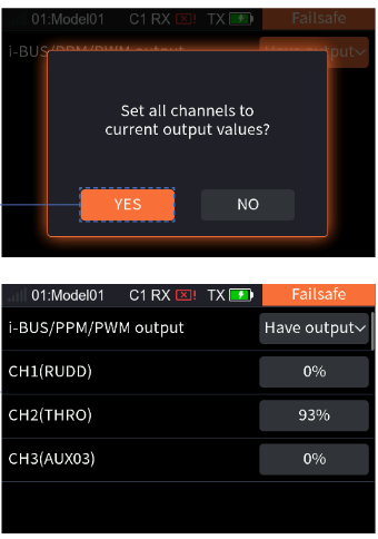
- Go to Home > Main Menu > RX Menu, select Failsafe, then short press the scroll wheel to enter.
- Set all channels: Select Have output, short press the scroll wheel, and the system will pop up a prompt interface. Adjust the corresponding controls to the desired positions and hold them if needed. Select Yes on the pop-up prompt interface and short press the scroll wheel again; the failsafe setting for all channels is completed.
- Continue to set an individual channel if needed: Select the channel to be set, short press the scroll wheel. Select the appropriate value or adjust the corresponding control to the desired position and hold it. Short press the scroll wheel to save the settings.
Notes:
- Because the S.BUS signal contains failsafe flag bits, the failsafe information can be transmitted to the subsequent devices by the failsafe flag bits rather than by the No Output state. The subsequent devices respond according to the analysed failsafe flag bits.
- For PWM/PPM/i-BUS signals without failsafe flag bits, it supports setting the output signal to OFF in case of failsafe, transmitting the failsafe information to the subsequent devices by the No Output state.
- It is Not Set by default; the receiver will then not output when the RC signal is lost.
13.3Sensor
This function can display the sensor information received by the receiver on the transmitter. The transmitter and receiver communicate via an ANT 2 Way binding, and all sensors connected to the receiver can find their corresponding information under this function menu.
13.3.1Display Sensors
This list displays all sensor data connected to this transmitter, including sensor ID, type and real-time value.
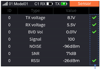
- [Type]: shows the sensor type.
- [ID]: displays the sensor's number. By default, number zero in the list includes TX Voltage, RX Voltage, Signal strength, RSSI, Noise and SNR. No. 1 is the first external sensor connected to the receiver, and so on, up to 15 sensors in total.
- [Value]: displays the data returned by a sensor.
This list is displayed in real time. When the receiver is connected to a sensor, the list will be refreshed to display the new sensor's data. When the sensor is disconnected, its data will not be displayed.
Supported i-BUS series sensors: FS-CAT01 (altitude), FS-CPD01 (speed / magnetic), FS-CPD02 (speed / light), FS-CVT01 (voltage), FS-CTM01 (temperature) and FS-CGPS01 (GPS).
Taking the FS-SR8 receiver bound with the FS-ST16 transmitter as an example, the sensor is connected to the SENS connector of the FS-SR8. If multiple sensors are connected simultaneously, the next sensor can be connected to the IN connector of the previous sensor.

Speed sensor (FS-CPD01, FS-CPD02)
The speed sensor is applied to test the speed of the motor. "Motor speed" indicates that the sensor is testing the motor speed; "0rpm" is the speed measurement value.
Magnetic induction speed sensor (FS-CPD01):
- Connect the FS-CPD01 sensor to the receiver or to other sensors connected to the receiver using the same method as shown above.
- Place the sensor next to the magnet, which is fixed at the position of the axial rotation to be tested (e.g. inside the wheel hub of the model car).
- Place the sensor within 2 mm of the magnet, with the south or north pole of the magnet parallel to the sensor.
- Turn on the transmitter, and select [Sensor] > [Display Sensor]. Turn the gear. When the [Type] column shows "RPM" and the RPM value (0rpm) in the [Value] column changes, the installation is successful. Otherwise, repeat the above steps.
Light induction speed sensor (FS-CPD02):
- Connect the FS-CPD02 to the relevant device, with the same connection method as above.
- Fix the sensor and the reflective sticker at the position of the axial rotation to be tested. Keep the sticker flat and perpendicular to the sensor probe. Keep a moderate distance between the sensor probe and the sticker.
- Turn on the transmitter, and select [Sensor] > [Display Sensor]. Turn the gear. When the [Type] column shows "RPM" and the RPM value (0rpm) in the [Value] column changes, the installation is successful. Otherwise, repeat the above steps.
Temperature sensor (FS-CTM01)
Used to monitor the temperature of various components. The temperature of the component can be monitored via the transmitter. Alarms can be set.
- Connect the FS-CTM01 to the receiver or other sensors using the same method as used with other sensors.
- Use spongy double-sided tape to stick the temperature probe to the part you wish to monitor (such as motor or battery).
- Turn on the transmitter, enter [Sensor] > [Display Sensors] and rotate the wheel. If the [Type] column displays "Temperature" and the [Value] column displays a temperature, the installation was successful; otherwise repeat the above steps.
Voltage sensor (FS-CVT01)
It is used to monitor the model's battery voltage. The battery voltage can be monitored through the transmitter. Alarms can be set.
- Connect the FS-CVT01 following the same steps as above.
- Insert the red and black wire pins into the plug of the battery used for testing. The red wire is the power anode and the black wire is the power cathode. Make sure to connect correctly.
- Turn on the transmitter, enter the [Sensor] > [Display Sensors] menu and rotate the wheel. If the [Type] column displays "External Voltage" and the [Value] column displays a voltage, the installation was successful; otherwise repeat the above steps.
13.3.2Sensors Set
This section describes how to configure the sensors displayed on the Home 2 page, including whether the sensors should alarm and the high and low alarm values.
- [Select sensor]: Used to select the sensor that needs to be set and displayed on the Home 2 page.
- [Home display]: Set whether the current sensor is displayed on the main page. A maximum of 4 sensors can be displayed on the Home page; if more than 4 are selected, a pop-up message will appear saying "No more than four sensors can be displayed!"
- [Alarm]: Used to set whether to enable sensor alarms. Once enabled, you can set the low alarm value or the high alarm value.
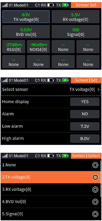
Introducing the setting of related parameters using the transmitter voltage as an example:
- Select [TX voltage] to enter the setting interface.
- To change the sensor displayed here, select [Select sensor] to enter the settings interface, choose the sensor you want to display, and then short press the EXIT button to return to the previous interface.
- Select [Home display], short press the scroll wheel to switch [Yes] or [No].
- Select [Alarm], short press the scroll wheel to switch [Yes] or [No].
- Select [Low alarm], set the low alarm value as needed.
- Select [High alarm], set the high alarm value as needed.
Notes:
- The setting only takes effect for the current sensor. When you select a different sensor, the set parameters will be cleared.
- If the system sound and alarm sound are turned off ([Setup] > [Sound] > [Sys/Alarm] / [Alarm]), the alarm will not sound even if the alarm is enabled here.
For the other sensor settings, refer to the related setting of TX voltage.
13.3.3Speed And Distance
This function is used to monitor wheel revolutions and the distance traveled.
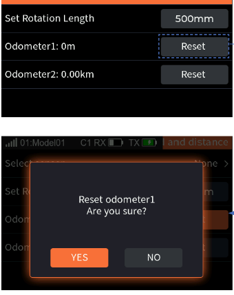
- [Select Sensors]: Selects the target sensor. If the sensor and receiver are connected, it will appear in this menu automatically. If multiple speed sensors are connected, the default display is the speed sensor with the smallest ID number.
- [Set Rotation Length]: If a speed sensor is installed on the wheel, you need to define the rotation length. This length will be used to calculate the distance traveled. Short press the Up or Down button to adjust the radius.
- [Odometer1]: Odometer1 is used to record the distance traveled.
- [Odometer2]: Odometer2 is used to record the total driving distance, that is, the cumulative distance of all sessions.
Select the reset option to the right of [Odometer1] or [Odometer2], and a system pop-up window will appear. Choose [Yes] to reset Odometer1 or Odometer2.
13.3.4BVD Voltage Calibration
There may be a voltage difference between the voltage detected by the receiver and the actual voltage of the battery. Use this function to set a calibration coefficient for the receiver to make the voltage displayed on the interface equal to the battery voltage, namely, the sum of the detection voltage and the calibration coefficient is equal to the voltage displayed on the interface.
The BVD voltage detection range is from 0 to 70 V. Battery Voltage displays the battery voltage detection value returned by the receiver in real time.
Notes:
- This function is available for ANT receivers with BVD function, which must be in two-way communication with the transmitter.
- Pay attention to correctly connecting the BVD cable and the anode and cathode of the battery as shown in the diagram below.
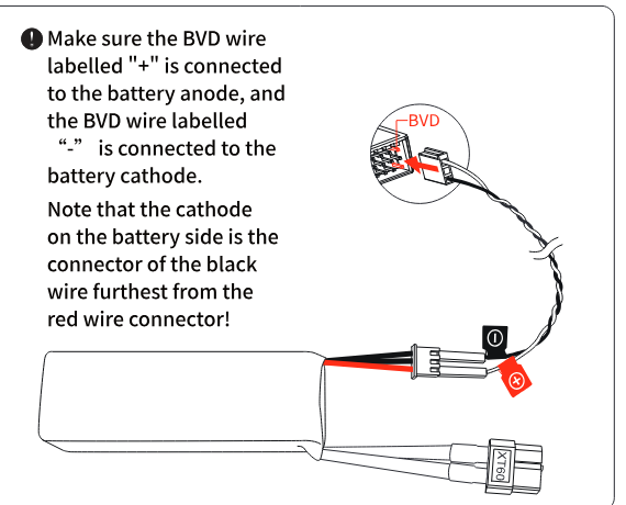
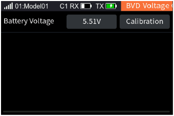
Setup: Connect the BVD detection line correctly before setting, and then perform the calibration. Note: Please refer to the voltage value of a multimeter for calibration.
- Select [BVD Voltage Calibration] to enter the function setting interface.
- Then change the battery voltage value as needed. Select [Calibration]. After successful calibration, click "YES" in the pop-up window reminder.
13.3.5Height Zero
Reset the altitude sensor data.
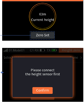
- [Select sensor]: Select the altitude sensor that needs to be zeroed. If multiple altitude sensors are connected, the default display is the altitude sensor with the smallest ID number.
- [Zero Set]: Used to set the current height to 0 meters.
- Select [Select sensor], and then choose the altitude sensor as needed.
- Select [Zero Set], and then select "Yes" in the pop-up window that appears.
13.3.6GPS Set
This function is applicable to the FS-CGPS01 module. You can view the GPS-related information received on the transmitter side, such as speed, distance, relative altitude, elevation, latitude and longitude. You can also calibrate the GPS, select the time zone, and reset the starting point.
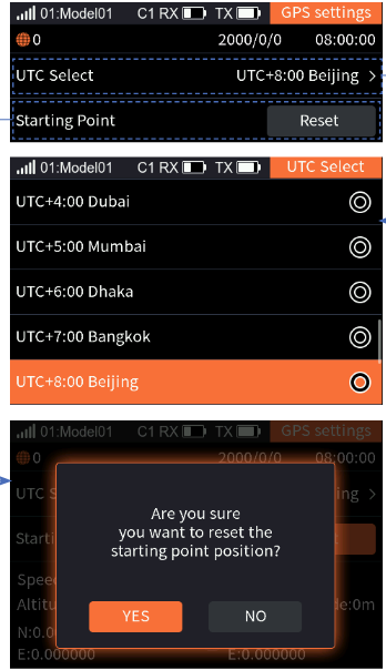
- [UTC Select]: Displays the set time zone. Enter the time zone selection interface, then press the EXIT button to return to the previous interface.
- [Starting Point]: Selecting [Reset] will reset the starting point position.
GPS display
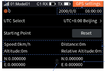
- Positioning icon: shows whether the positioning is successful. If the icon is green, the positioning is successful; if gray, it has failed.
- Satellite count: displays the number of satellites returned by GPS. When the number of satellites is more than 10, the GPS positioning accuracy is high; otherwise there is positioning error.
- Date and time in 24-hour clock.
- The real-time latitude and longitude of the model, and of the starting point.
- Model data display area.
13.4i-BUS Set
This function is used to set up the i-BUS expansion module.
The i-BUS function is mainly used for servo expansion. If a cable is too short or the number of servos exceeds the outputs of the receiver, the i-BUS serial bus receiver provides a convenient option for expansion. When using the i-BUS serial bus receiver, make sure that it is powered separately to ensure that the servos have sufficient power. Note that the transmitter and receiver must be bound bidirectionally.
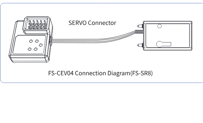
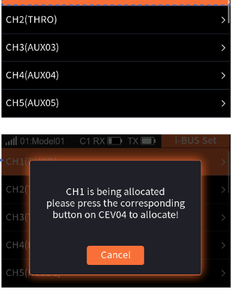
- The transmitter is in two-way communication with the receiver.
- Connect the FS-CEV04 to the SERVO connector of the receiver.
- Select [i-BUS Set] to enter the setting interface.
- Select the channel to be assigned, and a prompt window will appear.
- Use an appropriate tool to press the K1, K2, K3 or K4 button on the FS-CEV04 to assign the selected channel to C1, C2, C3 or C4.
- After successful assignment, the prompt window will be displayed on the interface; then short press the scroll wheel to exit.
- Repeat the above steps as needed.
14System Menu
The system menu is mainly used to set various system functions of the transmitter, such as screen settings, sound settings, and so on.
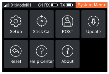
14.1Setup
This section introduces the settings of some system functions. Access them via [Main Menu] > [System Menu] > [Setup].
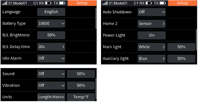
14.1.1Language
Used to set the system language of the transmitter, with two options: [English] and [简体中文].
Setup: Select [Language], short press the scroll wheel to switch the language.
14.1.2Battery Type
You can set the battery type of the transmitter's power supply: [18650], [2S LiPo] and [Other]. When the system is in a low voltage state, it will give an alarm, to avoid accidents caused by long-term operation under low voltage. If the battery type is 18650 or 2S LiPo, the system will enter the low voltage state when the battery voltage is lower than 7.2 V, and the interface will display the relevant prompts.
Setup: Select [Battery Type], select the battery type in the dropdown box according to the actual situation, and then short press the scroll wheel. If you select [Other], the default alarm value is 7 V; you can set the alarm value according to the user manual of the battery you are using.
14.1.3B/L Brightness
Used to set the backlight of the transmitter. The adjustment range is 10%–100%.
Setup: Select [B/L Brightness], change the percentage as needed, then short press the scroll wheel to save the settings.
14.1.4B/L Delay Time
Used to set the duration of the display's bright state. When there is no operation of the EXIT button, MENU button, scroll wheel or power button, the display will enter the off-screen state after exceeding the set time. Operating the EXIT button, MENU button, scroll wheel or power button again will turn the screen back on. You can select [5s], [10s], [30s], [1m], [2m], [5m], [10m] and [ON]. The default setting is [30s].
Setup: Select [B/L Delay time], select the appropriate backlight delay as needed, then short press the scroll wheel to save the settings.
14.1.5Idle Alarm
Set whether to enable idle alarm reminders and the alarm time. You can select [3m], [5m], [10m], [20m] and [Off]. The default setting is [3m].
Setup: Select [Idle Alarm], select the appropriate idle alarm time, then short press the scroll wheel to save the settings.
14.1.6Auto Shutdown
Set whether to enable the auto-off function and the auto-off time. Once this function is activated, if there is no operation on the transmitter and no two-way communication with the receiver within the set time, the transmitter will automatically shut down. You can select [5m], [10m], [30m] and [Close]. The default setting is [5m].
Setup: Select [Auto Shutdown], select the appropriate auto-off time, then short press the scroll wheel to save the settings.
14.1.7Home 2
Please refer to 5. System Interface for this function.
14.1.8Power Light
Set to turn on or off the LED light at the power button. The power light is turned on by default when the device is powered on.
Setup: Select [Power Light], short press the scroll wheel to switch [On] or [Off].
14.1.9Main Light
Set the colors and brightness levels of the main ambient lights. You can set whether to turn off the upper ambient lights, use them as a battery indicator or throttle indicator, and adjust the color and brightness of the ambient lights.
- Battery indicator: When the light is green, the battery voltage is greater than or equal to the alarm value; otherwise it is red.
- Throttle indicator: When the light is blue, the throttle stick is in the neutral range; otherwise the light fades between blue and red.
- Ambient light color: Red, Green, Blue, Yellow, Cyan, Purple, White or Dazzle.
- Brightness level: default 50%, adjustable within the range of 10%–100%.
- Go to Home > Main Menu > System Menu, select Main light, and press the scroll wheel to enter.
- Select the appropriate function item and press the scroll wheel to confirm, then short press the EXIT button to return to the previous interface.
- Select the brightness and short press the scroll wheel. Then scroll the wheel to set the desired value, then press the scroll wheel.
14.1.10Auxiliary Light
The functions and settings are the same as for the main ambient lights; refer to the description of 14.1.9 Main Light.
14.1.11Sound
Set the volume level and type of the speaker sound. Volume level setting range: 10–100%, the default value is 50%. You can set [Sys/ALM], [System], [Alarm] and [Off]. The default setting is [Sys/ALM].
- Select [Sound], select the desired sound type in the drop-down menu as needed, and then short press the scroll wheel.
- Select the percentage and set an appropriate value as needed, then short press the scroll wheel to save the settings.
14.1.12Vibration
Set the intensity level and type of the vibration motor. Intensity level setting range: 10–100%, the default value is 50%. You can set [Sys/ALM], [System], [Alarm] and [Off]. The default setting is [Sys/ALM]. Please refer to 14.1.11 Sound for this function.
14.1.13Units
Choose the units to use for length and temperature. Unit of length: metric or imperial; the default is Metric. Unit of temperature: Celsius or Fahrenheit; the default is Celsius.
Setup: Select [Units], select the unit of length or unit of temperature, short press the scroll wheel to switch the unit.
14.2Stick Cal
Please refer to 4.4 Stick Cal for this function.
14.3POST
Used to set whether to enable the self-check prompt for the controls at startup and the failsafe prompt at startup. Both are enabled by default.
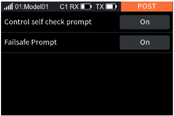
- Select [Control self check prompt], short press the scroll wheel to switch [On] or [Off].
- Select [FailsafePrompt], short press the scroll wheel to switch [On] or [Off].
14.4Firmware Update
To put the transmitter into the updating state. In case of updating the firmware of the transmitter, use this function to put the transmitter into updating mode first, then upgrade the transmitter's firmware.
The firmware can be updated in the following two ways: through the Flysky Assistant (the Flysky Assistant is available on the Flysky official website www.flysky-cn.com), or by following the steps below:
- Download and open the latest official firmware.
- Connect the transmitter to the computer via the USB Type-C cable.
- Go to Home > Main Menu > System Menu, select Firmware Update, then short press the scroll wheel; a prompt screen will pop up, select Yes and short press the scroll wheel to enter the updating state.
- After completing the above steps, click Update in the firmware window on the computer to start the update.
- The transmitter will power on again when the updating process is finished. Then remove the USB Type-C cable and close the firmware.
- Do not unplug the USB Type-C cable while the firmware is updating.
- After a firmware update the receiver may not be connected. If this is the case, the receiver firmware needs to be updated.
14.5Factory Reset
Used to restore all settings and parameters of the transmitter; that is, all model data and settings are restored to their default state.
Setup: Select [Reset]; the system displays a pop-up window, select [Yes] to complete.
14.6Help Center
This function interface provides the product's manual, as well as the official website, Facebook, YouTube and X (Twitter). Users can choose the corresponding QR code as needed and scan it to view the information.
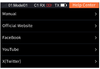
14.7About
This function contains basic information such as product name, firmware version, version date, hardware and RF library version.
15Switch Allocation
How to set a switch for certain functions.
15.1Normal ON/OFF Switch Setting
If the function does not require switch control, it can be set to "--", at which point the function will always be disabled. Alternatively, it can be set to an active state, in which case the function will always be enabled. In the execution of the trainer function, the switching state of the student transmitter can be set through this function.
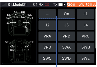
- Enter the Switch Allocation interface.
- Select [ON] or [--].
- Select "--" to cancel the switch if a physical control on the transmitter is assigned.
Note: Action switches do not support the setting of Normal ON or Normal OFF.
15.2Position Switch Setting
For two-position and three-position switches, you can set any position to On or Off.
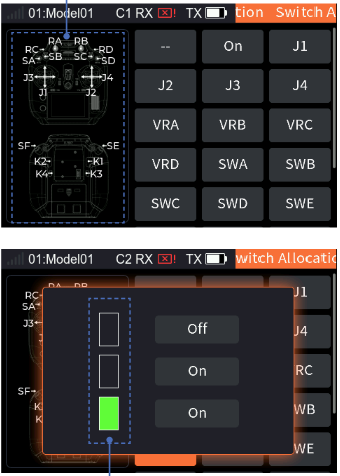
- Enter the Switch Allocation interface.
- Scroll the wheel as needed to select the appropriate control or toggle the corresponding control, such as SWC, then short press the scroll wheel.
- Scroll the wheel to select any position of [ON] or [OFF], set the ON/OFF state of this position.
Notes:
- All switches starting with "SW" are position switches.
- For the Timer and Sensor this switch function is an "Action Switch": the action of switching from the "OFF" position to the "ON" position is a valid action, and the function is a one-time switch.
15.3Continuous Switch Setting
For continuous controls such as a stick or knob, the ON or OFF position can be set more flexibly according to different setting types.
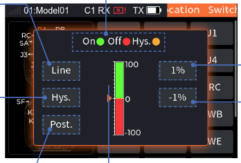
- Line / Sym.: short press the scroll wheel to toggle between Line (linear) and Sym. (symmetric).
- Hys. / Box: short press the scroll wheel to toggle between Hys. (hysteresis) and Box.
- Post. / Reve.: short press the scroll wheel to toggle between positive and reverse.
- The triangle marks the present position of the control.
- The first value shows the position of ON; short press the scroll wheel to set the present position of the control to ON. The second value shows the position of OFF; short press the scroll wheel to set the present position of the control to OFF.
- The control status display area shows the switch state: green means ON, red means OFF, yellow means Hys. (hysteretic).
Linear/Symmetric mode
[Line]: sets the ON or OFF position separately for the whole control travel. [Sym.]: sets the ON or OFF position symmetrically for the upper part or the lower part with the neutral point as the reference. You can switch the ON or OFF position by Posit. (positive) or Reve. (reverse).
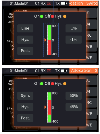
Taking the Post. switch state as an example (the reverse state is set the same way):
- Enter the Switch Allocation interface.
- Scroll the wheel as needed to select the appropriate control or toggle the corresponding control, such as VRD, then short press the scroll wheel.
- Select [Line] to switch the type.
- Set the switch status to [Post.].
- Turn the VRD to a suitable position, select the first function box to the right of the control status display area, and short press the scroll wheel to set this position to "On".
- Turn the VRD to a suitable position, select the second function box to the right of the control status display area, and short press the scroll wheel to set this position to "Off".
Hysteresis/Box mode
[Hys.]: sets the border for ON or OFF only. You can set the hysteresis interval (yellow) for the border. When the control position is in the hysteresis interval, the previous state is kept. [Box]: Box has no hysteresis interval. You can set 2 border values for the on/off area. When the switch is outside this area, the switch state is opposite to the state inside this area. You can switch the ON or OFF position by Posit. or Reve.
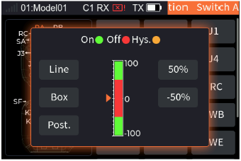
- Enter the Switch Allocation interface.
- Scroll the wheel as needed to select the appropriate control or toggle the corresponding control, such as VRD, then short press the scroll wheel.
- Select [Hys.] to switch the type.
- Set the switch status to [Post.].
- Turn the VRD to a suitable position, select the first function box to the right of the control status display area, and short press the scroll wheel to set this position to "On".
- Turn the VRD to a suitable position, select the second function box to the right of the control status display area, and short press the scroll wheel to set this position to "Off".
15.4Self-resetting Button Switch
For this type of button, you can set two states: On and Off. The state is opposite when the button is pressed and when the button springs back.
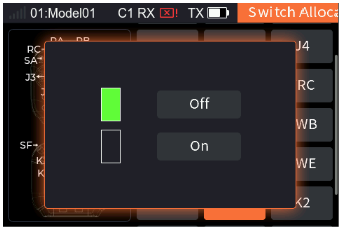
- Enter the Switch Allocation interface.
- Scroll the wheel as needed to select the appropriate control or toggle the corresponding control, such as K2, then short press the scroll wheel.
- Scroll the wheel to select any position of [ON] or [OFF], set the ON/OFF state of this position.
15.5Logic Switch Setting
Provides the interface for selecting logic switches. Users can preview the corresponding component switches and logical relations of the logic switches, and can select the preview box to enter the logic switch setting interface to reset the logic switches.
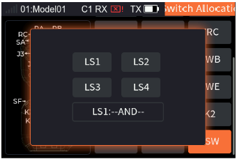
- Enter the Switch Allocation interface.
- Scroll the wheel to select [LSW]; a pop-up screen appears, choose the logic switch you want to set, then short press the scroll wheel to save the settings.
16User Customization
The system supports user replacement of the ratchet throttle plate, assembly and disassembly of the mobile bracket, replacement of the gimbal assembly, and installation of the SMA antenna as needed.
16.1Replace the Throttle Plate
The FS-ST16 transmitter comes with a smooth (non-ratchet) throttle plate out of the factory. If you want to use a ratchet throttle plate, please follow the steps below to replace it.
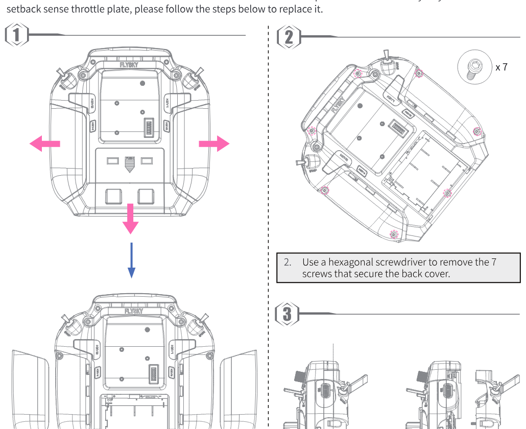
- Remove the battery cover and the left and right grip soft rubber.
- Use a hexagonal screwdriver to remove the 7 screws that secure the back cover.
- Separate the front cover from the back cover.
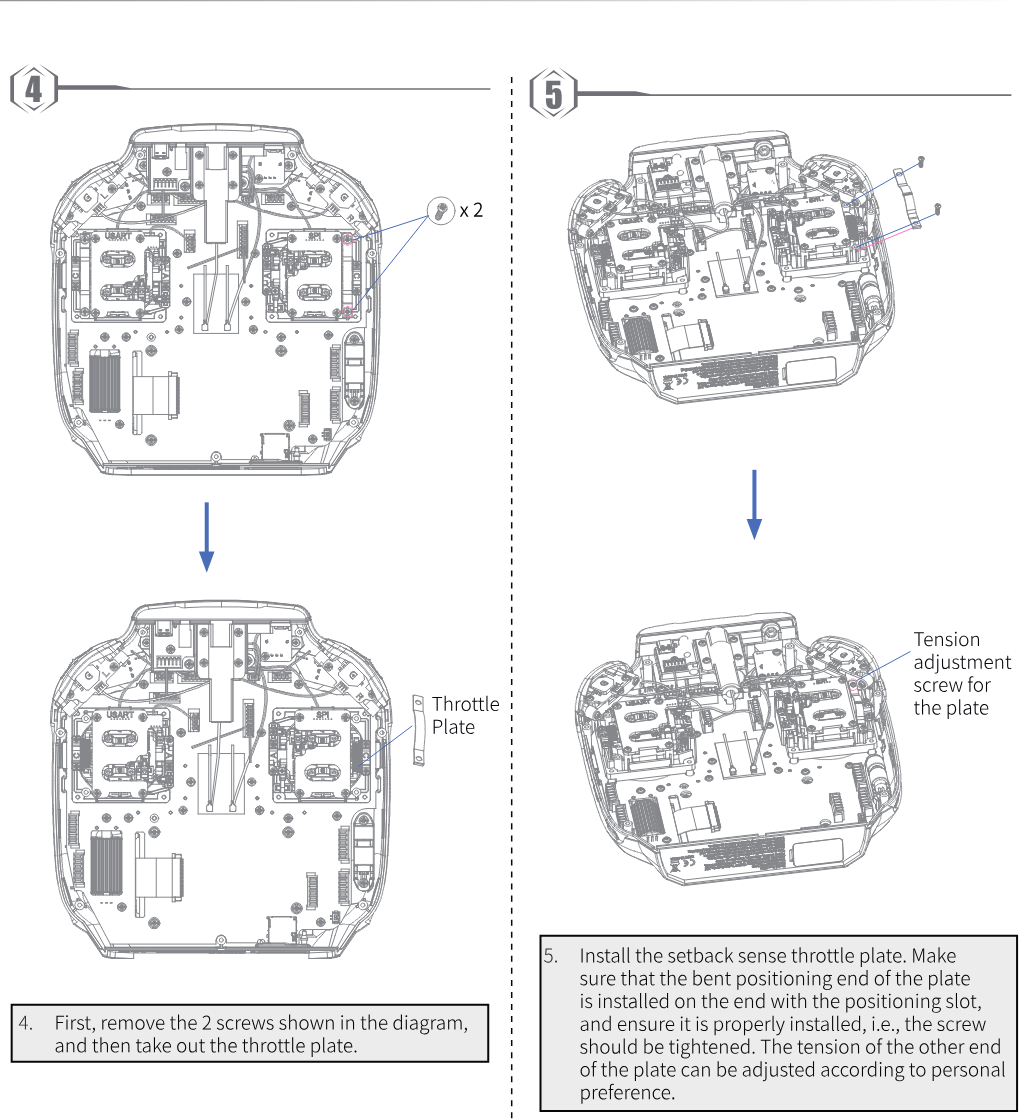
- First, remove the 2 screws shown in the diagram, and then take out the throttle plate.
- Install the ratchet throttle plate. Make sure that the bent positioning end of the plate is installed on the end with the positioning slot, and ensure it is properly installed, i.e., the screw should be tightened. The tension of the other end of the plate can be adjusted according to personal preference.
- Reattach the transmitter's back cover, tighten the screws, and reinstall the left and right grip soft rubber.
16.2Throttle Stick (non-centering and centering)
Follow these steps to change a non-centering stick to a centering stick.
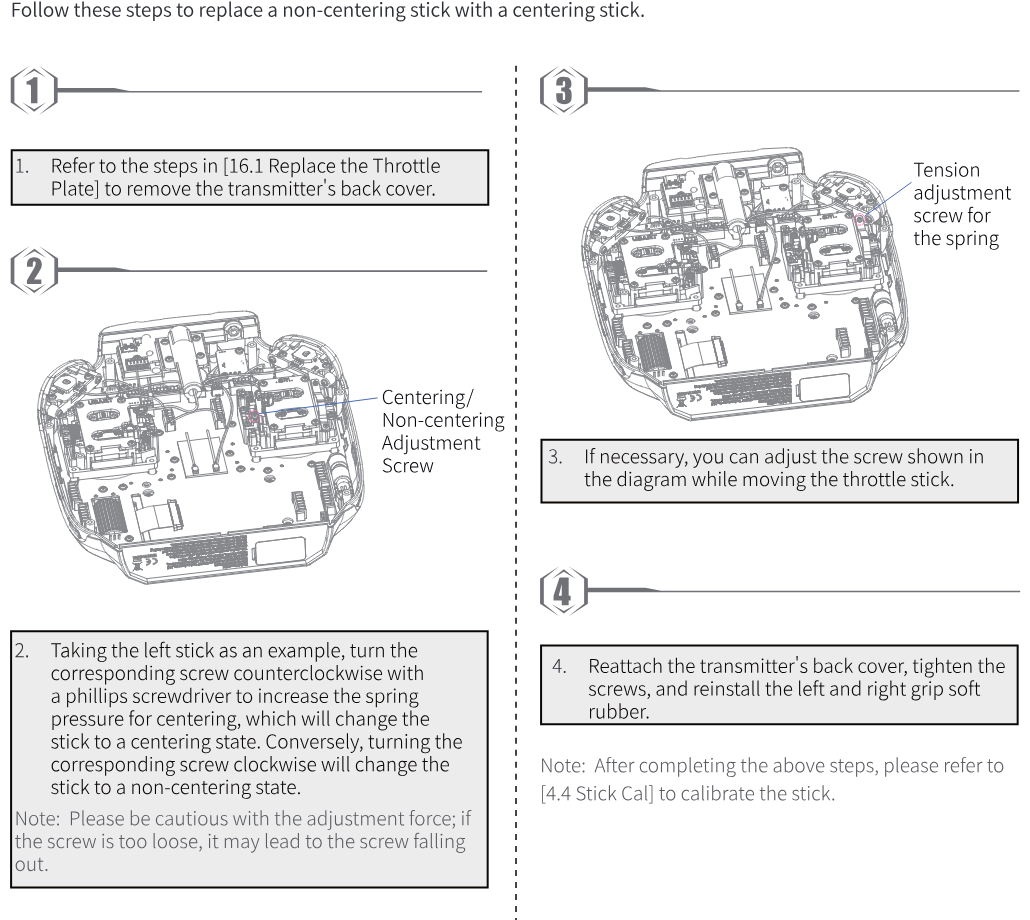
- Refer to the steps in 16.1 Replace the Throttle Plate to remove the transmitter's back cover.
- Taking the left stick as an example, turn the corresponding screw counterclockwise with a Phillips screwdriver to increase the spring pressure for centering, which will change the stick to the centering state. Conversely, turning the corresponding screw clockwise will change the stick to the non-centering state. Note: Please be cautious with the adjustment force; if the screw is too loose, it may fall out.
- If necessary, you can adjust the screw shown in the diagram while moving the throttle stick.
- Reattach the transmitter's back cover, tighten the screws, and reinstall the left and right grip soft rubber.
Note: After completing the above steps, please refer to 4.4 Stick Cal to calibrate the stick.
16.3Mobile Bracket Installation
You can use the mobile bracket to mount devices such as smartphones onto the transmitter.
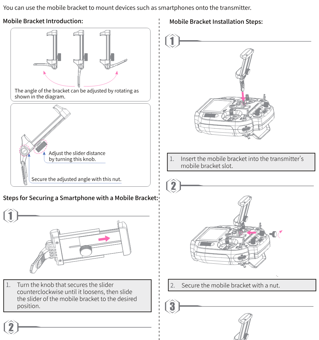
Mobile bracket introduction: the angle of the bracket can be adjusted by rotating as shown in the diagram. Adjust the slider distance by turning the knob. Secure the adjusted angle with the nut.
Mobile bracket installation steps:
- Insert the mobile bracket into the transmitter's mobile bracket slot.
- Secure the mobile bracket with a nut.
- After completion, it should look like the diagram shown.
Steps for securing a smartphone with the mobile bracket:
- Turn the knob that secures the slider counterclockwise until it loosens, then slide the slider of the mobile bracket to the desired position.
- Place the smartphone or other device in the center of the bracket, ensuring balance on both sides to prevent the device from falling off due to the display being skewed to the left or right.
- Adjust the slider distance and tighten the knob to secure the mobile device in place.
16.4Gimbal Assembly Replacement
This transmitter comes with a Hall gimbal assembly by default. If you want to replace it with a potentiometer version gimbal assembly, follow these steps to secure it onto the transmitter.
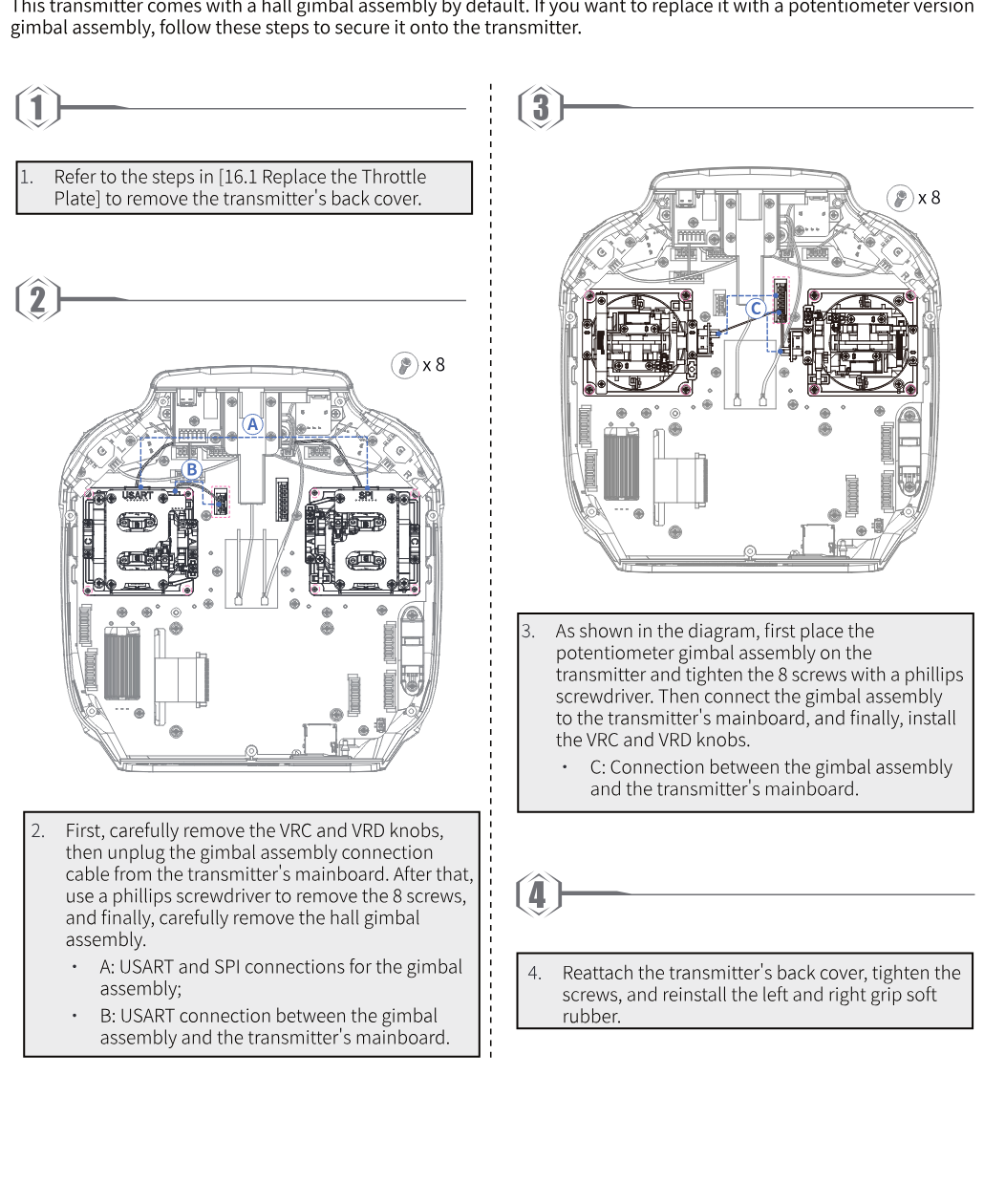
- Refer to the steps in 16.1 Replace the Throttle Plate to remove the transmitter's back cover.
- First, carefully remove the VRC and VRD knobs, then unplug the gimbal assembly connection cable from the transmitter's mainboard. After that, use a Phillips screwdriver to remove the 8 screws, and finally, carefully remove the Hall gimbal assembly. A: USART and SPI connections for the gimbal assembly; B: USART connection between the gimbal assembly and the transmitter's mainboard.
- As shown in the diagram, first place the potentiometer gimbal assembly on the transmitter and tighten the 8 screws with a Phillips screwdriver. Then connect the gimbal assembly to the transmitter's mainboard, and finally install the VRC and VRD knobs. C: Connection between the gimbal assembly and the transmitter's mainboard.
- Reattach the transmitter's back cover, tighten the screws, and reinstall the left and right grip soft rubber.
16.5Antenna Assembly Installation
If you have purchased the 2.4G antenna assembly (inner screw, inner hole), the installation procedure is described below.
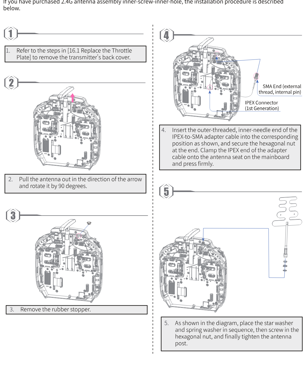
- Refer to the steps in 16.1 Replace the Throttle Plate to remove the transmitter's back cover.
- Pull the antenna out in the direction of the arrow and rotate it by 90 degrees.
- Remove the rubber stopper.
- Insert the outer-threaded, inner-pin end of the IPEX-to-SMA adapter cable into the corresponding position as shown, and secure the hexagonal nut at the end. Clamp the IPEX end of the adapter cable onto the antenna seat on the mainboard and press firmly.
- As shown in the diagram, place the star washer and spring washer in sequence, then screw in the hexagonal nut, and finally tighten the antenna post.
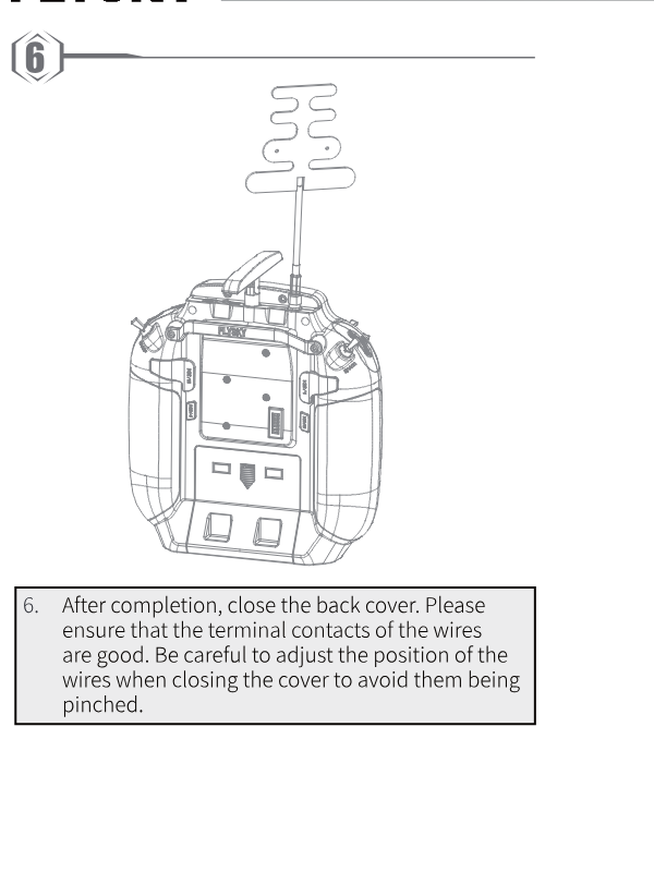
- After completion, close the back cover. Please ensure that the terminal contacts of the wires are good. Be careful to adjust the position of the wires when closing the cover to avoid them being pinched.
17Specifications
This chapter includes the specifications of the FS-ST16 transmitter and the FS-SR8 receiver.
17.1Transmitter Specifications
| Product model | FS-ST16 |
| Compatible receiver | FS-SR8 and other receivers with ANT protocol |
| Compatible RC model | Airplanes, cars or boats |
| Number of channels | 16 |
| RF | 2.4 GHz ISM |
| Maximum power | < 20 dBm (e.i.r.p.) (EU) |
| RF protocol | ANT |
| Resolution | 4096 |
| Data connector | USB Type-C, 3.5 mm audio jack (DSC), SD card slot |
| Input power | 6–9 V DC; 2 × 18650 / 2S LiPo |
| Distance | No less than 1500 m (air distance without interference) |
| Antenna | Two antennas (one built-in antenna and one external folding antenna) |
| Display | 3.5 inch 320 × 480 full-dot color non-touch IPS screen |
| Online update | Yes |
| Temperature range | −10 ℃ to +60 ℃ |
| Humidity range | 20 % to 95 % |
| Color | Black |
| Language | Chinese or English |
| Weight | 665 g |
| Dimensions | 224.1 × 180 × 101.3 mm |
| Charging jack | Yes (Type-C port) |
| Certifications | CE, FCC ID: 2A2UNST1600 |
17.2Receiver Specifications
| Product model | FS-SR8 |
| Compatible transmitter | FS-ST16 and other transmitters with ANT protocol |
| Compatible RC model | Fixed-wing aircraft, helicopters, gliders, delta-wing airplanes, multicopters, racing drones, engineering vehicles, bait boats, robots or cars |
| Number of channels | 8 |
| RF | 2.4 GHz ISM |
| Maximum power | < 20 dBm (e.i.r.p.) (EU) |
| RF protocol | ANT |
| Resolution | 4096 |
| Data output | PWM/PPM/i-BUS/S.BUS |
| Operating voltage | 3.5–9 V DC |
| Distance | No less than 1000 m (air distance without interference) |
| Antenna | Two antennas |
| Display | LED |
| Online update | Yes |
| Temperature range | −10 ℃ to +60 ℃ |
| Humidity range | 20 % to 95 % |
| Color | Black |
| Weight | 10 g |
| Dimensions | 44.8 × 26.6 × 11.3 mm |
| Certification | CE, FCC ID: 2A2UNSR800 |
18Package Contents
This section contains the packaging list of the FS-ST16 transmitter. Since different versions may have different configurations, please consult your dealer for specific details.
| Number | Name | Quantity |
|---|---|---|
| 1 | FS-ST16 transmitter | 1 |
| 2 | FS-SR8 receiver | 1 |
| 3 | Quick start guide | 1 |
| 4 | USB Type-C cable | 1 |
| 5 | Ratchet throttle plate | 1 |
19Certification
19.1FCC Compliance Statement
This device complies with Part 15 of the FCC Rules. Operation is subject to the following two conditions: (1) this device may not cause harmful interference, and (2) this device must accept any interference received, including interference that may cause undesired operation.
Warning: Changes or modifications not expressly approved by the party responsible for compliance could void the user's authority to operate the equipment.
This equipment has been tested and found to comply with the limits for a Class B digital device, pursuant to Part 15 of the FCC Rules. These limits are designed to provide reasonable protection against harmful interference in a residential installation. This equipment generates, uses and can radiate radio frequency energy and, if not installed and used in accordance with the instructions, may cause harmful interference to radio communications. However, there is no guarantee that interference will not occur in a particular installation. If this equipment does cause harmful interference to radio or television reception, which can be determined by turning the equipment off and on, the user is encouraged to try to correct the interference by one or more of the following measures:
- Reorient or relocate the receiving antenna.
- Increase the separation between the equipment and receiver.
- Connect the equipment into an outlet on a circuit different from that to which the receiver is connected.
- Consult the dealer or an experienced radio/TV technician for help.
19.2EU DoC Declaration
Hereby, ShenZhen FLYSKY Technology Co., Ltd. declares that the radio equipment type FS-ST16 is in compliance with Directive 2014/53/EU. The full text of the EU declaration of conformity is available at the following internet address: www.flyskytech.com/info_detail/10.html
19.3Environmentally Friendly Disposal
Old electrical appliances must not be disposed of together with the residual waste, but have to be disposed of separately. Disposal at the communal collecting point by private persons is free of charge. The owner of old appliances is responsible for bringing the appliances to these collecting points or to similar collection points. With this little personal effort, you contribute to recycling valuable raw materials and the treatment of toxic substances.
- RISK OF EXPLOSION IF THE BATTERY IS REPLACED BY AN INCORRECT TYPE. DISPOSE OF USED BATTERIES ACCORDING TO THE INSTRUCTIONS.
- Replacement of a battery with an incorrect type can defeat a safeguard (for example, in the case of some lithium battery types).
- Disposal of a battery into fire or a hot oven, or mechanically crushing or cutting of a battery, can result in an explosion.
- Leaving a battery in an extremely high temperature surrounding environment can result in an explosion or the leakage of flammable liquid or gas.
- A battery subjected to extremely low air pressure may result in an explosion or the leakage of flammable liquid or gas.
19.4RF Exposure Statement
This equipment complies with FCC radiation exposure limits set forth for an uncontrolled environment. This transmitter must not be co-located or operating in conjunction with any other antenna or transmitter. These requirements set a SAR limit of 4 W/kg averaged per ten grams of tissue. The highest SAR value is reported under this standard during product certification for use when properly worn on the limbs.
19.5CE SAR Statement
This equipment complies with Directive 2014/53/EU radiation exposure limits set forth for an uncontrolled environment. The end user must follow the specific operating instructions for satisfying RF exposure compliance. This transmitter must not be co-located or operating in conjunction with any other antenna or transmitter.
The portable device is designed to meet the requirements for exposure to radio waves established by the European Union market (France). These requirements set a SAR limit of 4 W/kg averaged over ten grams of tissue. The highest SAR value reported under this standard during product certification for use when properly worn on the limbs is 1.149 W/kg.
19.6FCC SAR Statement
The radiated output power of this device is below the FCC radio frequency exposure limits. Nevertheless, the device should be used in such a manner that the potential for human contact is minimized during normal operation. The exposure standard for wireless devices employs a unit of measurement known as the Specific Absorption Rate, or SAR. The SAR limit set by the FCC is 1.6 W/kg. Tests for SAR are conducted using standard operating positions accepted by the FCC with the device transmitting at its highest certified power level in all tested frequency bands. Although the SAR is determined at the highest certified power level, the actual SAR level of the device while operating can be well below the maximum value. This is because the device is designed to operate at multiple power levels so as to use only the power required to reach the network. In general, the closer you are to a wireless base station antenna, the lower the power output. To avoid the possibility of exceeding the FCC radio frequency exposure limits, human proximity to the antenna should be minimized.
For body-worn operation, this model has been tested and meets the FCC RF exposure guidelines when used with an accessory designated for this product or when used with an accessory that contains no metal and that positions the device a minimum of 0 mm from the body. The maximum SAR value is 1.509 W/kg when the device is used 0 mm from the user.
Figures and illustrations in this manual are provided for reference only and may differ from the actual product appearance. Product design and specifications may be changed without notice.