
1Safety
1.1Safety Symbols
Pay close attention to the following symbols and their meanings. Failure to follow these warnings could cause damage, injury or death.
| Danger | Not following these instructions may lead to serious injuries or death. |
| Attention | Not following these instructions may lead to minor injuries. |
1.2Safety Guide
- Do not use the product at night or in bad weather like rain or thunderstorm. It can cause erratic operation or loss of control.
- Do not use the product when visibility is limited.
- Do not use the product on rain or snow days. Any exposure to moisture (water or snow) may cause erratic operation or loss of control.
- Interference may cause loss of control. To ensure the safety of you and others, do not operate in the following places: near any site where other radio control activity may occur; near power lines or communication broadcasting antennas; near people or roads; on any pond when passenger boats are present.
- Do not use this product when you are tired, uncomfortable, or under the influence of alcohol or drugs. Doing so may cause serious injury to yourself or others.
- The 2.4GHz radio band is limited to line of sight. Always keep your model in sight as a large object can block the RF signal and lead to loss of control.
- Never grip the transmitter antenna during operation. It significantly degrades signal quality and strength and may cause loss of control.
- Do not touch any part of the model that may generate heat during operation, or immediately after use. The engine, motor or speed control may be very hot and can cause serious burns.
- Misuse of this product may lead to serious injury or death. To ensure the safety of you and your equipment, read this manual and follow the instructions.
- Make sure the product is properly installed in your model. Failure to do so may result in serious injury.
- Make sure to disconnect the receiver battery before turning off the transmitter. Failure to do so may lead to unintended operation and cause an accident.
- Ensure that all motors operate in the correct direction. If not, adjust the direction first.
- Make sure the model flies within a certain distance. Otherwise, it could cause loss of control.
2Introduction
The FS-i6X transmitter and FS-iA6 receiver constitute a 6-channel 2.4GHz AFHDS 2A digital proportional computerized R/C system. It is compatible with fixed-wing and helicopters.
2.1System Features
The AFHDS 2A (Automatic Frequency Hopping Digital System Second Generation) developed and patented by FLYSKY is specially developed for all radio control models. Offering superior protection against interference while maintaining lower power consumption and high reliable receiver sensitivity, FLYSKY's AFHDS technology is considered to be one of the leaders in the RC market today.
| Bidirectional Communication | Capable of sending and receiving data, each transmitter is capable of receiving data from temperature, altitude and many other types of sensors, servo calibration and i-BUS support. |
| Multi-channel Hopping Frequency | This system's bandwidth ranges from 2.408GHz to 2.475GHz. This band is divided in 135 channels. Each transmitter hops between 16 channels (32 for Japanese and Korean versions) in order to reduce interference from other transmitters. |
| Omni-directional Gain Antenna | The high efficiency omni-directional high gain antenna cuts down on interference, while using less power and maintaining a strong reliable connection. |
| Unique ID Recognition System | Each transmitter and receiver has its own unique ID. Once the transmitter and receiver have been paired, they will only communicate with each other, preventing other systems accidentally connecting to or interfering with the system's operation. |
| Low Power Consumption | The system is built using highly sensitive low power consumption components, maintaining high receiver sensitivity, while consuming as little as one tenth the power of a standard FM system, dramatically extending battery life. |
2.2Transmitter Overview
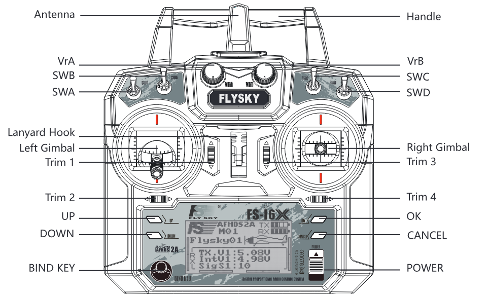
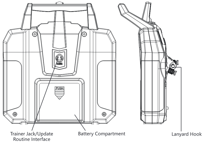
2.2.1Transmitter Antenna
- For best signal quality, make sure that the antenna is at about a 90 degree angle to the model. Do not point the antenna directly at the receiver.
- Never grip the transmitter antenna during operation. It significantly degrades the RF signal quality and strength and may cause loss of control.
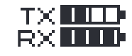
2.2.2Battery Indicator
The status indicator is used to indicate the power and status of the transmitter and receiver. If a receiver is not connected or bound to the transmitter no battery status will be displayed for the receiver.
2.2.3Trims
There are 4 trims affecting stick functionality, one for ailerons (Channel 1), elevator (Channel 2), throttle (Channel 3) and rudder (Channel 4). Each time a trim is toggled, the trim will move one step. It is possible to make quicker trim adjustments by holding the trim in the desired direction. When the trim position reaches the middle, the transmitter beeps in a higher tone.
2.3Receiver Overview
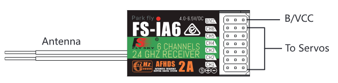
2.3.1Receiver Antenna
- For best signal quality, ensure that the receiver is mounted away from motors or metal parts.
2.3.2Connectors
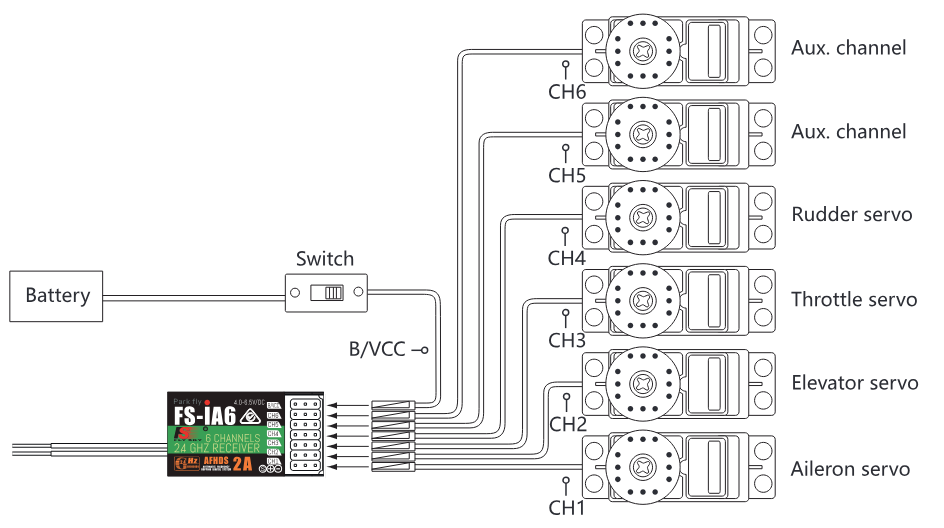
The connectors are used to connect the parts of model and the receiver.
- CH1 to CH6: used to connect the servos, power or other parts.
- B/VCC: used to connect the bind cable for binding, and the power cable during normal operation.
3Getting Started
Before operation, install the battery and connect the system as instructed below.
3.1Transmitter Battery Installation
- Only use specified battery.
- Do not open, disassemble, or attempt to repair the battery.
- Do not crush/puncture the battery, or short the external contacts.
- Do not expose to excessive heat or liquids.
- Do not drop the battery or expose to strong shocks or vibrations.
- Always store the battery in a cool, dry place.
- Do not use the battery if damaged.
Follow the steps to install the transmitter battery:
- Open the battery compartment.
- Insert 4 fully-charged AA batteries into the compartment. Make sure that the batteries make good contact with the battery compartment's contacts, with the correct polarity.
- Replace the battery compartment cover.
3.2Connecting the Receiver and Servos
Connect the receiver and the servos as indicated in the connector diagram in section 2.3.2.
4Operation Instructions
After setting up, follow the instructions below to operate the system.
4.1Power On
Follow the steps below to turn on the system:
- Check the system and make sure that the batteries are fully charged and installed properly, and that the receiver is off and correctly installed.
- Toggle the power switch to its upward position.
- Connect the receiver power supply to the B/VCC port on the receiver.
The system is now powered on. Operate with caution, or serious injury could result.
4.2Binding
The transmitter and receiver have been pre-bound before delivery. If you are using another transmitter or receiver, follow the steps below to bind the transmitter and receiver:
- Connect the supplied bind cable to the B/VCC port on the receiver.
- Insert power into any other port.
- Hold the bind key while powering on the transmitter to enter bind mode.
- Remove the power and bind cable from the receiver. Then connect the power cable to the B/VCC port.
- Check the servos' operation. If anything does not work as expected, restart this procedure from the beginning.
4.3Pre-use Check
Before operation, perform the following steps to check the system:
- Check to make sure that all servos and motors are working as expected.
- Check operating distance: one operator holds the transmitter, and another one moves the model away from the transmitter. Check the model and mark the distance from where the model starts to lose control.
- Stop operation if any abnormal activity is observed.
- Make sure the model does not go out of range.
- Sources of interference may affect signal quality.
4.4Changing Stick Modes
Usually the stick with the self centering feature on both axes will be mapped to the Elevator, while the other to the Throttle. The functions of the sticks in respective modes are shown below:
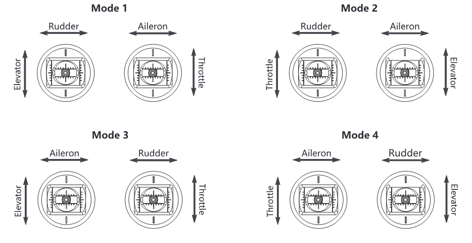
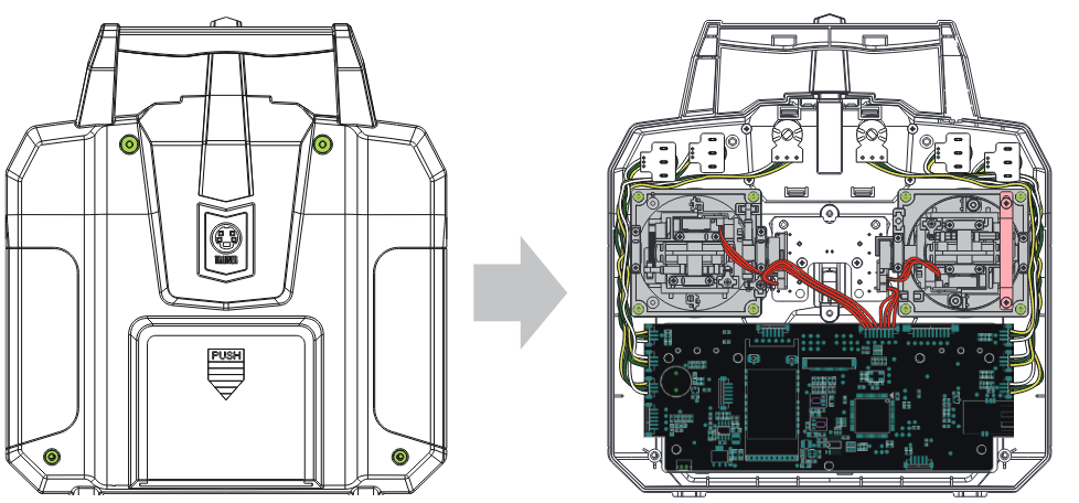
When switching between modes one and two it is necessary to reverse the gimbals' positions to ensure that throttle is on the correct side. To switch the sticks:
- Take the battery out from the transmitter, loosen the four screws that hold the rear cover, shown in green on the left.
- Carefully take the back off the transmitter and disconnect the cables connected to it.
- Unscrew the screws around the gimbals, marked in green in the picture on the right.
- Switch the gimbals to the opposite side. Make sure the gimbals have been rotated 180 degrees so that the wires are facing towards the middle of the system.
- Reconnect the wires connecting the back to the front, then reattach the back and tighten the screws.
- Turn on the transmitter, go to Main Menu, select "System Setup" and navigate to "Sticks mode", then make sure the correct stick mode is selected. From the main menu enter "System Setup" and select "Display" and move the joystick to make sure that the channel moves in the correct direction.
4.5Power Off
Follow the steps below to turn off the system:
- Disconnect the receiver power.
- Toggle the transmitter's power switch to its low position.
- Make sure to disconnect the receiver power before turning off the transmitter. Failure to do so may lead to damage or serious injury.
5Function Descriptions
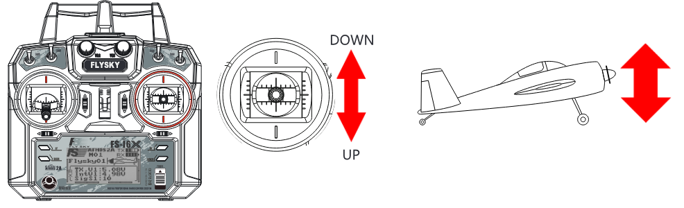
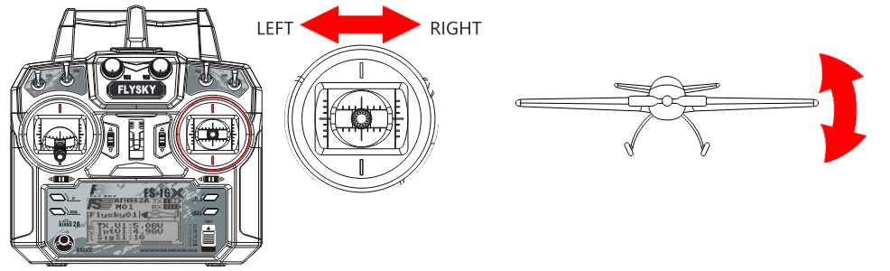
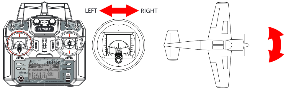
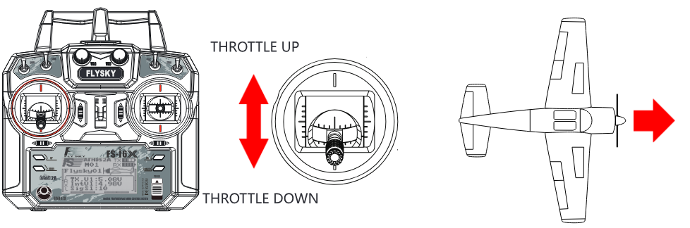
5.1Flight Controls (Default Mode 2)
The sticks are used for controlling the aircraft, each stick has 2 functions. The right stick controls pitch and roll, the left stick controls throttle and yaw.
5.2Reverse Function
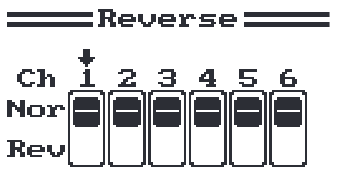
The reverse function changes a channel's direction of movement in relation to its input. For example, if a servo has to be mounted upside down due to space restrictions within a model, this function can be used to correct its movement so that it matches up with the user controls.
Setup:
- To change between normal and reverse, press the "OK" key until the desired channel is selected, then use the "UP" and "DOWN" keys to change the setting. Nor = Normal, Rev = Reverse.
- Hold the "CANCEL" key to save and return to the previous menu.
- To return to default settings press and hold the "OK" key for 3 seconds. Press and hold the "CANCEL" key to save.
5.3End Points
The end points function changes the range of movement available to a channel. This can be used to prevent damage to a model when a servo moves too far, potentially leading to damage to pushrods etc.
The left box is the low end point, the right box is the high end point, marked below as low being red and blue being high.
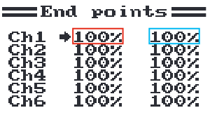
Setup:
- Press "OK" to change channels.
- Move the channel using its stick or knob to select the low or high side.
- Use the "UP" and "DOWN" keys to increase or decrease the value.
- Hold the "CANCEL" key to save and return to the previous menu.
- To return to default settings press and hold the "OK" key for 3 seconds. Press and hold the "CANCEL" key to save.
5.4Display
This function displays the model's channel output in real time.
- Make sure the model engine is powered off while the test function is activated. If powered on, it will rev up and cause unexpected results.
- Make sure the model does not go out of range.
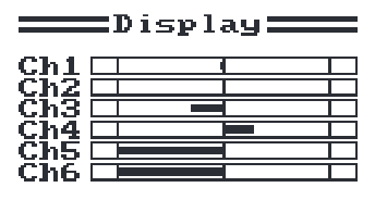
Setup:
- Hold the "OK" key to enable channel scrub mode. In this mode the channels will sweep through their entire range of motion.
- Press the "CANCEL" key to exit.
5.5Aux Channels
The auxiliary channels function can be used to assign switches to extra channels to control additional parts of a model such as landing gear or lights.
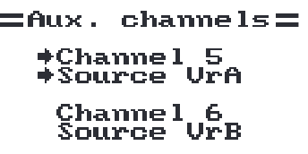
Setup:
- Press "OK" to change channels.
- Use the "UP" and "DOWN" keys to select a source (Switch, Knob or None).
- Hold the "CANCEL" key to save and return to the previous menu.
5.6Subtrim
Subtrim changes the center point of the channel. For example, if a model's rudder is slightly out of alignment, the subtrim could be used to fix this.
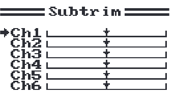
Setup:
- Press "OK" to change channels.
- Use the "UP" and "DOWN" keys to change the subtrim position.
- Hold the "CANCEL" key to save and return to the previous menu.
- To return to default settings press and hold the "OK" key for 3 seconds until the channel returns to the center. Press and hold the "CANCEL" key to save.
5.7Dual rate/exp.
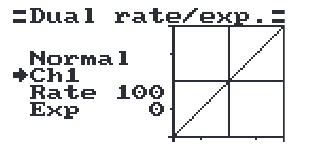
The dual rate/exp. function only applies to channels 1, 2 and 4.
[Dual Rate]: Dual Rate reduces or increases the difference between the highest and lowest possible value. For example if applied to the rudder (set to a throw of 10cm), before changing the settings, when you move your stick to 1/2 you would get 5cm rudder movement; if you move the stick 1/4 of the way, the rudder will move 2.5cm, so at 100% there is a direct, linear relationship of stick movement and surface movement.
If a setting of 50% is entered then moving the stick all the way in one direction will only give 1/2 of the surface movement and 1/2 stick movement will only produce 1/4 surface movement. This has the effect of reducing how responsive the rudder is when the stick is moved, effectively reducing the range of movement available to the servo. This function is usually assigned to a condition so that it can be turned on and off during flight.
[Exp. (Exponential)]: Exponential changes the relationship between stick movement and surface movement by creating a curve. When in use the stick movement and surface movement are no longer linear, so the stick has a different response at different positions. For example this is useful when needing less reaction during a take-off but more reaction when in the air.
Setup:
- Press "OK" to change between settings.
- Use the "UP" and "DOWN" keys to change the channel/rate/exp depending on the selected setting.
- Hold the "CANCEL" key to save and return to the previous menu.
- To return a setting to default, press and hold the "OK" key for 3 seconds. Press and hold the "CANCEL" key to save.
5.8Throttle Curve
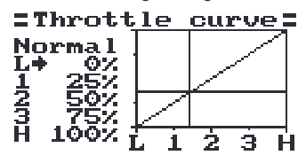
This function enables the user to adjust the ratio between stick and servo movement using a linear line or non-linear curves.
This is useful when wanting to change how the throttle reacts between different stick positions, for example having a smaller throttle change when the stick is between 0-30%, then a larger throttle change between 30% and 100%. If your model's throttle is not linear, it is also possible to use this function to create a more linear movement.
This function uses 5 points to change the throttle curve, L being the low and H being the high.
Setup:
- Press "OK" to change between points.
- Use the "UP" and "DOWN" keys to change the point position.
- Hold the "CANCEL" key to save and return to the previous menu.
- To return a setting to default, press and hold the "OK" key for 3 seconds. Press and hold the "CANCEL" key to save.
5.9Mixes
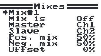
This function is used to create a mix between channels. For example if at low throttle some automated flap movement was desired then it is possible to create a mix to do this. This system can have up to 3 different mixes.
Setup:
- Use the "UP" and "DOWN" keys to select a mix.
- Use the "OK" key to change between settings.
- Select a master channel; this channel will control the slave channel.
- Select a slave channel to be controlled by the master.
- Set the positive and negative mix. This setting controls how much the slave channel will move in relation to the master's movement; if set to 50% the slave will move half the amount of the master.
- Set the offset. The offset changes the center of the slave channel in relation to the master.
- Hold the "CANCEL" key to save and return to the previous menu.
- To return a setting to default, press and hold the "OK" key for 3 seconds. Press and hold the "CANCEL" key to save.
5.10Elevon
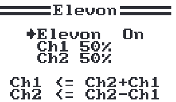
The elevon function is used for planes that combine the elevons and ailerons together.
Setup:
- Use "UP" and "DOWN" to turn the function on and off.
- Use the "OK" key to change between settings.
- Use the "UP" and "DOWN" keys to change the percentage.
- To return a setting to default, press and hold the "OK" key for 3 seconds. Press and hold the "CANCEL" key to save.
5.11V Tail
The V Tail function is used for planes that use a V-tail configuration.
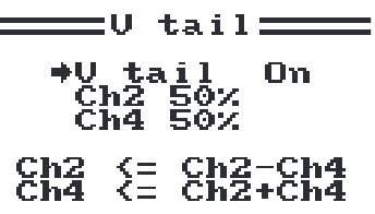
Setup:
- Use "UP" and "DOWN" to turn the function on and off.
- Use the "OK" key to change between settings.
- Use the "UP" and "DOWN" keys to change the percentage.
- To return a setting to default, press and hold the "OK" key for 3 seconds. Press and hold the "CANCEL" key to save.
5.12Assign Switches
This function enables you to assign switches to Fly mode, Idle mode and Throttle hold.
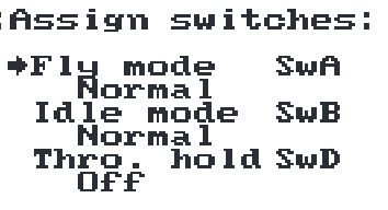
Setup:
- Use the "OK" key to change between settings.
- Use the "UP" and "DOWN" keys to change the switch assignment.
- Press and hold the "CANCEL" key to save.
- Switches must be turned on in the Aux Switches function (7.13) to be available for assignment.
5.13Throttle Hold
This function is used with gas powered models in order to stop stalls when not in use.
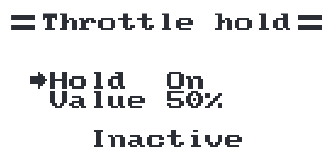
Setup:
- Use the "OK" key to change between settings.
- Use the "UP" and "DOWN" keys to turn the function on or off and increase and decrease the hold percentage.
- To return a setting to default, press and hold the "OK" key for 3 seconds. Press and hold the "CANCEL" key to save.
- This function will not work unless assigned to a switch. The switch can be used to enable or disable the function. Please refer to Assign Switches (5.12) for more details on how to assign a switch to a function.
- Switches must be turned on in the Aux Switches function (7.13) to be available for assignment.
- This function must be assigned to a switch in the Assign Switches function.
6Helicopter Functions
6.1Pitch Curve
The pitch curve function is for programming the response of the helicopter's blades' collective pitch, which controls the amount of lift the helicopter has. This function's output is shown on the graph, with points along the bottom (L, 1, 2, 3, H) and collective pitch up the side (0-100%). When the throttle stick is moved its position will be shown in real time.
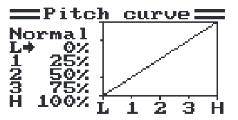
Setup:
- Use the "OK" key to cycle between points.
- Use the "UP" and "DOWN" keys to change the percentage (all changes are shown in real time in the graph).
- To return to default settings press and hold the "OK" key for 3 seconds, press and hold the "CANCEL" key to save.
6.2Swashplate Mix
The swashplate mix function sets the relative movement between each servo controlling movement of the swashplate controlling aileron, elevator and pitch.
Setup:
- Press the "OK" key to cycle through aileron, elevator and pitch.
- Use the "UP" and "DOWN" keys to change the percentage.
- Press and hold the "CANCEL" key to save and exit.
- To return to default settings press and hold the "OK" key until the currently selected parameter returns to 50%, and press and hold the "CANCEL" key to save.
6.3Gyroscope
The gyroscope function uses a gyroscope to correct for torque produced by changes in engine speed, pitch and wind etc., which can cause issues with yaw control. If not corrected each of these variables could cause the RC helicopter to spin, sometimes quite violently.
This function has 2 settings, Gyro (On/Off) and Value (%). The Mode shows the state of the Idle up function (this function needs to be assigned to a switch).
Setup:
- Use the "OK" key to cycle between "Gyro" and "Value"; select "Gyro" and press the "UP" or "DOWN" key to toggle on or off.
- Select "Value" and use the "UP" and "DOWN" arrow keys to change the percentage.
- To return to default settings press and hold the "OK" key until the currently selected parameter returns to 50%, and press and hold the "CANCEL" key to save.
7System
7.1Model Select
Use this function to select stored models: use the "UP" and "DOWN" keys to choose a model and press and hold the "CANCEL" key to save and exit. The system can store up to 20 models.
7.2Model Name
This function renames the currently selected model.
Setup:
- Use the "UP" and "DOWN" keys to select a letter or number, then press the "OK" key to confirm.
- To save press and hold the "CANCEL" key.
To return to default press and hold the "OK" key for 3 seconds, press and hold the "CANCEL" key to save.
7.3Type Select
This function changes the type of the currently selected model, including airplane and helicopter with different types of swashplates.
| Helicopter swashplate type | Available functions |
|---|---|
| Swash 140° | Pitch Curve, Swashplate Mix, Gyroscope |
| Swash 120° | Pitch Curve, Swashplate Mix, Gyroscope |
| Swash 90° | Pitch Curve, Swashplate Mix, Gyroscope |
| Variable pitch | Pitch Curve, Gyroscope |
| Fixed pitch | Gyroscope |
Setup:
- To change the model type press the "UP" and "DOWN" keys to select the model type, then press and hold the "CANCEL" key to save and exit.
7.4Model Copy
This function copies one model to another model slot.
Setup:
- Use the "UP" and "DOWN" keys to select the model you want to copy.
- Use the "OK" key, then use the "UP" and "DOWN" keys to select the slot to copy the model to.
- Press and hold the "OK" key to confirm. The system will display a prompt asking "Are you sure"; use the "UP" or "DOWN" key to select Yes and press "OK" again to confirm.
7.5Model Reset
This function resets the current model to the default settings.
Setup:
- Use the "UP" and "DOWN" keys to select a model. Press the "OK" key to confirm.
- The system will display a prompt asking "Are you sure"; use the "UP" or "DOWN" key to select Yes and press the "OK" key again to confirm.
7.6Trainer Mode
Trainer mode is used to take control of a slave system when a switch is in the off position. This function will only work when two systems are linked via the trainer lead.
Setup (this function must be assigned to a switch and will only be inactive when the switch is on):
- Use the "UP" and "DOWN" keys to turn the function on and off.
- Use the "OK" key, then use the "UP" and "DOWN" keys to select a switch.
- Press and hold the "CANCEL" key to save and exit.
7.7Student Mode
Student mode is used when another system is connected as a master (trainer). When this mode is active all settings will be bypassed and the system will only function through the master.
Setup:
- To enable the function press "OK" then select Yes. The system will return to the previous menu.
- To exit student mode repeat this process.
7.8Sticks Mode
There are 4 available stick modes; each stick mode changes the stick functions.
For example when using stick mode 2 the left stick controls throttle on the vertical axis and rudder on the horizontal axis; however in stick mode 3 the vertical axis controls elevator and the horizontal axis controls aileron. These modes are largely down to personal preference.
Setup:
- Use the "UP" and "DOWN" keys to select a stick mode.
- Press and hold the "CANCEL" key to save and exit.
- To return to default settings press and hold the "OK" key for 3 seconds, press and hold the "CANCEL" key to save.
7.9LCD Brightness
Setup:
- Use the "UP" and "DOWN" keys.
- Press and hold "CANCEL" to save and exit.
- To return to default settings press and hold the "OK" key for 3 seconds, press and hold the "CANCEL" key to save.
7.10Firmware Ver.
This function displays the current firmware version.
7.11Firmware Update
This function updates the firmware using a USB to PS/2 connection lead.
Setup:
- First download the update from our website, http://www.flysky-cn.com.
- Connect the system to the computer via the supplied cable and press "OK" while in this function.
- Wait for Windows to recognise the system.
- Then open the update on the computer and press update.
- Once the update is finished cycle the system power.
7.12Factory Reset
This function resets the entire system back to its factory settings. To reset press "OK", then use the "UP" and "DOWN" keys to select Yes and press "OK" again.
7.13Aux Switches
This function both activates and deactivates switches/knobs as well as changing the amount of active channels the system will use. This is usually done when a new switch or knob has been added.
Setup:
- Use the "OK" key to cycle through the selection of switches and knobs.
- Use the "UP" and "DOWN" keys to turn the selected switch/knob on or off.
- Keep pressing the "OK" key until "Ch" is selected.
- Use the "UP" and "DOWN" keys to change the amount of active channels to match your current configuration.
- To return to default settings press and hold the "OK" key for 3 seconds, press and hold the "CANCEL" key to save.
8RX Setup
8.1RF Standard
This menu allows you to change the communication protocol for the transmitter. The available protocols are:
| RF Protocol | Receiver |
|---|---|
| AFHDS | R9B, R6B, R6C, GR3E, GR3F |
| AFHDS 2A | A3, A6, X6, iA4B, iA6, iA6B, iA10, iA10B |
To switch between AFHDS 2A and AFHDS:
- First navigate to the system menu by pressing and holding the "OK" key until the main menu opens; select "System Setup" by pressing the "OK" key again.
- Use the "DOWN" key to navigate to "RX setup" and press the "OK" key again to enter, then press the "OK" key one more time to select RF Standard.
- The system will display a prompt asking if you are sure; use the "UP" or "DOWN" key to select yes and press "OK".
- Then use the "UP" or "DOWN" key to select the desired RF standard and press and hold the "CANCEL" key until the system returns to the previous menu to save.
- Use the "UP" and "DOWN" keys to select a mode then press and hold the "CANCEL" key to save and exit.
8.2RX Battery
This function is used to change the battery monitor settings. This function can be switched to an external or internal sensor. There are 4 settings:
| External sensor / Internal sensor | The system has its own voltage sensor; however it is possible to change to an external sensor. |
| Low | Sets the low battery voltage; see your battery's user manual to set this setting. |
| Alarm | Sets the voltage level at which the system will alert the user if the battery gets too low. |
| High | Sets the voltage for the battery if it is full. |
- These settings affect how the system shows battery levels. If the high and low are incorrect the system's battery display will not be reliable.
8.3Failsafe
This function is used to protect the models and users if the receiver loses signal and therefore is no longer controllable.
All channels are listed in the failsafe menu. [Off] means that in case of a loss of signal, the corresponding servo will keep its last received position. If it displays a percentage, the servo will instead move to the selected position.
Setup:
- Use "UP" and "DOWN" to choose a channel and press "OK" to enter its failsafe settings.
- Use "UP" and "DOWN" to turn the failsafe on or off.
- Move the channel's control surface to the desired position and hold the "CANCEL" key to confirm and exit.
- To return to default settings press and hold the "OK" key for 3 seconds, use the "UP" and "DOWN" keys to select Yes, press and hold the "CANCEL" key to save.
You can set the failsafe position for all channels with the [All channels] button at once. To do so:
- Move all your channels to the desired position.
- Select [All channels].
- Once the failsafe has been set, a percentage will be displayed.
8.4Sensors List
This function displays all connected sensors and their outputs.
8.5Choose Sensors
This function changes which sensors will be displayed on the home screen. The home screen can display up to 3 sensors.
Setup:
- To add a sensor to the home screen, use the "OK" key to change the sensor slot, then use the "UP" and "DOWN" keys to select a sensor.
- To return to default settings press and hold the "OK" key for 3 seconds. Press and hold the "CANCEL" key to save and exit.
8.6Speed and Distance
This function is for setting up speed and distance sensors.
| Speed Sensor | If a sensor is connected, use the "UP" and "DOWN" arrow keys to select the desired sensor, then press and hold the "CANCEL" key to save. |
| Rotation Length | Measure the distance from the center of the prop to the distance sensor. Then use the "UP" and "DOWN" arrow keys to enter the length. Press and hold the "CANCEL" key to save. |
| Reset Odometer 1 + 2 | These settings return the odometer to 0. To reset select one, odometer 1 or 2, then press "OK". The system will display a prompt; select yes. |
| Reset odometer 1 | Resets odometer 1 to 0. Odometer 1 records the distance traveled during a session. Note that restarting the system will also reset odometer 1. |
| Reset odometer 2 | Resets odometer 2 to 0. Odometer 2 records the total distance traveled since last reset. This means that the distance over several sessions will be added together. |
8.7ASL Pressure
The set ASL (Above Sea Level) function is used to calibrate an altitude sensor. When an altitude sensor is connected, change the [Air pressure] setting until the altitude is at 0m.
Setup:
- Make sure that your TX and RX are bound and turned on.
- Set your model on the ground.
- Use the "UP" and "DOWN" keys to change the hPa value. If the system is showing a positive altitude, reduce the hPa value until the altitude reaches 0m. If the system is showing a negative altitude, increase the hPa value until it reaches 0m.
- To return to default settings press and hold the "OK" key for 3 seconds, press and hold the "CANCEL" key to save.
- Make sure that your model is at ground level during this process.
8.8Output Mode
PPM is capable of transferring all channels through one physical output. When [RX PPM output] is checked:
- When [PWM] is selected the receiver will output channels 1-6 via channels 1-6.
- When [PPM] is selected the receiver will output a standard PPM signal via the PPM interface.
To turn the function on press the "UP" or "DOWN" keys to turn the function on, then press and hold the "CANCEL" key to save and exit.
8.9i-BUS Setup
This function is used to set up the i-BUS module. The i-BUS module can be used to add servos to your model that may be too far away from the receiver.
Setup:
- Use the "UP" and "DOWN" keys to choose a channel and press "OK".
- Press the button on the i-BUS module that corresponds to the desired output; the system will then return to the previous menu.
- After setting up the desired channels press and hold the "CANCEL" key to save and exit.
8.10Servos Freq
This function sets the frequency that the receiver outputs to the servos. Check your servos' user manual to find the correct setting.
9System Customization
The FS-i6X's switches and knobs can be moved to other channels. Or if using receivers with more channels, the system can be expanded with extra switches or knobs.
By default, from left to right, the knobs are channels 5 and 6, the switches are 7, 8, 9 and 10.
| FS-A6 / FS-iA6B / FS-iA6 | 6CH |
| FS-iA10B | 6-10CH |

9.1Switching Channel Assignments
To change a switch or knob's channel, the system must be taken apart. The first step is taking the back cover off.
- Remove any batteries from the system and replace the battery cover.
- Remove the screws marked in green.
- Carefully pry the front and back apart; this may take some force.
- Carefully disconnect the cables connecting the front to the back.
- Make sure the screwdriver you are using is not too big or too small. Failure to do so could damage the head of the screw.
- Don't pull the pieces too far apart; doing so could damage cables attaching the front and back together.
- Make sure you keep the screws in a safe place.
- Make sure that the wires are fitted along beside each of the gimbals as shown.
- Make sure that all switches are installed with the correct orientation shown.
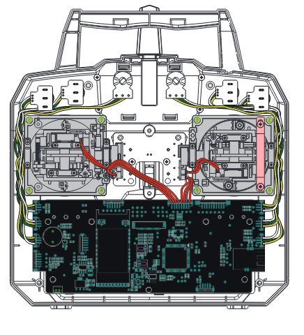
- On the circuit board each channel is labelled, making it easy to find the correct channel. Follow the cables leading from each connector to identify which switch or knob goes to each channel.
- Carefully remove the desired connectors from the board.
- Replace the desired switch/knob connectors into the corresponding channel slot.
- Do not pull on the wires themselves; doing so may damage the connector or wire.
Removing a switch:
- Take the transmitter apart following the above instructions.
- Remove the toggle's connector from the circuit board.
- Unscrew the plate holding the toggle in place on the front of the transmitter.
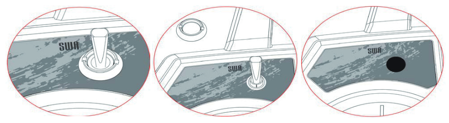
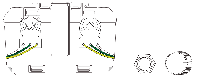
Removing a knob: remove the pot cover by slowly pulling on it; it should come off without much effort.
- Remove the 4 screws located on the back of the system and remove the back cover.
- Follow the knob's wire and disconnect it from the board.
- Gently remove the knob cap by pulling it up.
- Remove the nut holding the knob in place.
- Remove the knob.
Afterwards put the back cover back in place, squeeze the handle until the two pieces click together, and replace the cover screws.
9.2Activate Switch/Knob
Open the system menu, navigate to "Aux Switches" and press the "OK" key. Use the "OK" key to change switch/knob, then use the "UP" or "DOWN" keys to turn the switch on. The switch will now be available in the "Assign Switches" menu.
10Package Contents
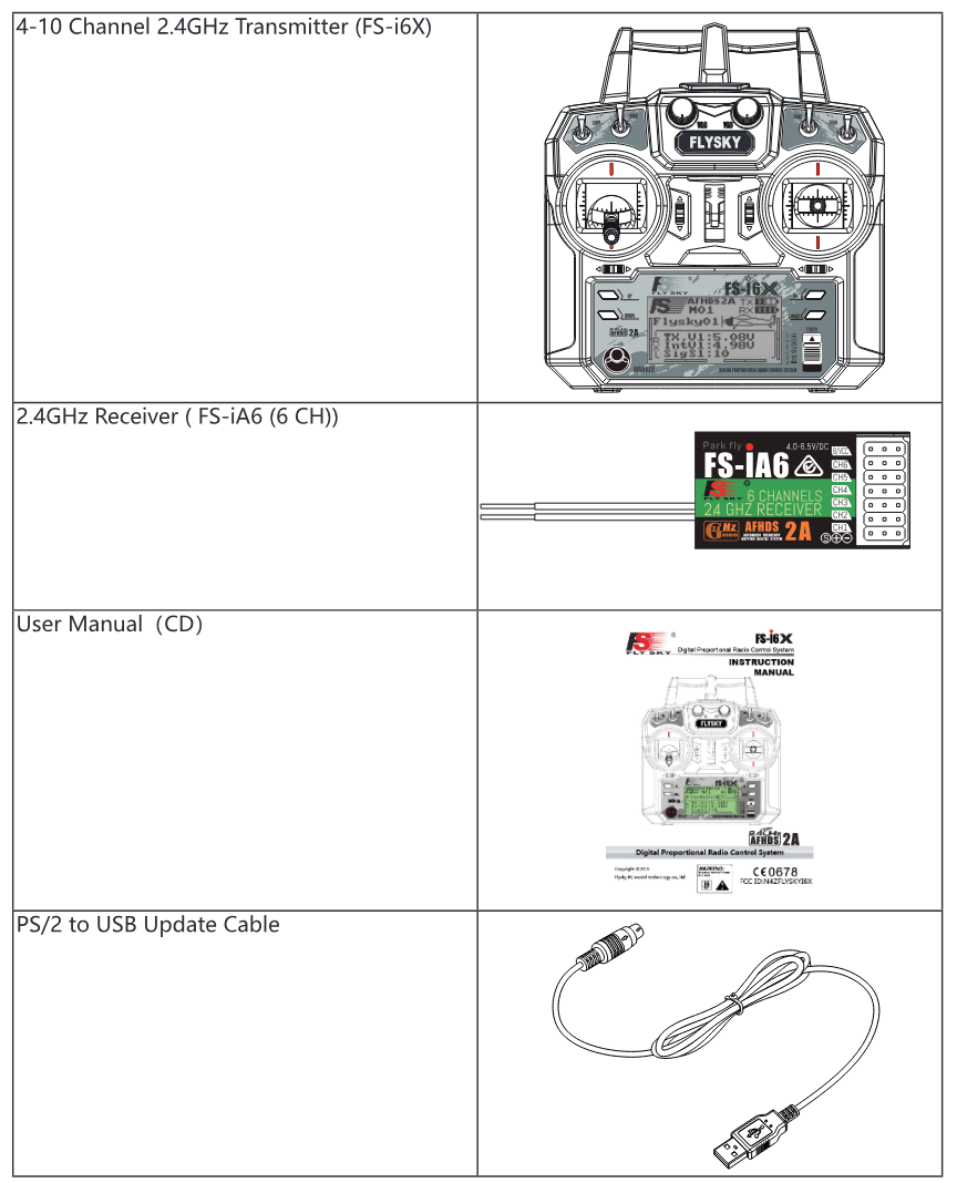
- 4-10 Channel 2.4GHz Transmitter (FS-i6X)
- 2.4GHz Receiver (FS-iA6, 6 CH)
- User Manual (CD)
- PS/2 to USB Update Cable
11Product Specification
11.1Transmitter Specification (FS-i6X)
| Channels | 6-10 (default 6) |
| Model type | Fixed-wing / Glider / Helicopter |
| RF range | 2.408-2.475GHz |
| RF power | < 20dBm |
| RF channels | 135 |
| Bandwidth | 500KHz |
| 2.4GHz system | AFHDS 2A / AFHDS |
| Modulation type | GFSK |
| Stick resolution | 4096 |
| Low voltage warning | < 4.2V |
| DSC port | PS/2 port, PPM |
| Chargeable | No |
| Antenna length | 26mm (dual antenna) |
| Weight | 392 g |
| Power | 6V DC, 1.5V AA × 4 |
| Display | STN transflective display, LCD 128×64 lattice, VA 73×39mm, LCD with white backlight |
| Size | 174×89×190mm |
| Online update | Yes |
| Colour | Black |
| Certificate | CE0678, FCC ID: N4ZFLYSKYI6X |
11.2Receiver Specification (FS-iA6)
| Channels | 6 |
| Model type | Fixed-wing / Glider / Helicopter |
| RF range | 2.408-2.475GHz |
| RF channels | 135 |
| RF receiver sensitivity | -105dBm |
| Bandwidth | 500KHz |
| 2.4GHz system | AFHDS 2A |
| Modulation type | GFSK |
| Power | 4.0~6.5V DC |
| Antenna length | 26mm (dual antenna) |
| Weight | 7g |
| Size | 40.4×21.1×15mm |
| i-BUS port | No |
| Data acquisition port | No |
| Colour | Black |
| Certificate | CE0678, FCC ID: N4ZFLYSKYIA6 |
Appendix 1: FCC Statement
This equipment has been tested and found to comply with the limits for a Class B digital device pursuant to part 15 of the FCC rules. These limits are designed to provide reasonable protection against harmful interference in a residential installation. This equipment generates, uses and can radiate radio frequency energy and, if not installed and used in accordance with the instructions, may cause harmful interference to radio communications. However, there is no guarantee that interference will not occur in a particular installation. If this equipment does cause harmful interference to radio or television reception, which can be determined by turning the equipment off and on, the user is encouraged to try to correct the interference by one or more of the following measures:
- Reorient or relocate the receiving antenna.
- Increase the separation between the equipment and receiver.
- Connect the equipment into an outlet on a circuit different from that to which the receiver is connected.
- Consult the dealer or an experienced radio/TV technician for help.
To assure continued compliance, any changes or modifications not expressly approved by the party responsible for compliance could void the user's authority to operate this equipment. (Example: use only shielded interface cables when connecting to computer or peripheral devices.)
This equipment complies with Part 15 of the FCC Rules. Operation is subject to the following two conditions: (1) this device may not cause harmful interference, and (2) this device must accept any interference received, including interference that may cause undesired operation.
Caution! The manufacturer is not responsible for any radio or TV interference caused by unauthorized modifications to this equipment. Such modifications could void the user's authority to operate the equipment.